4
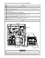
Setup of P.C. Board Switch
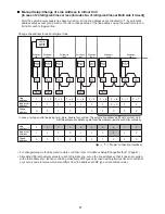
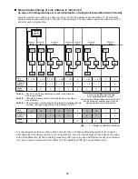
When the units controlled collectively are all digital inverter air conditioners, it is required to set up the terminator
resistor. (Collective control for units without VRF type air conditioner)
• Using SW01, set up the terminator resistor.
• Set up the terminator resistor to only interface connected to the indoor unit in the line with the least line
address No.
U1
U3
U2
U4
Central control
device
1
U1
U3
U2
U4
Central control
device
2 3
1 2 3
A B
U3 U4
Central control device: Max. 10 units
Refrigerant
line 1
Outdoor
unit
Indoor unit
“1 : 1 Model”
Connection Interface
(option)
Remote
controller
1 2 3
1 2 3
A B
U3 U4
Refrigerant
line 2
Remote
controller
1 2 3
1 2 3
A B
Refrigerant
line 3
Remote
controller
wiring
1 2 3
1 2 3
A B
Refrigerant
line 4
1 2 3
A B
U3 U4
Remote
controller
Wiring between indoor
and outdoor units
Wiring of central control system
Group control (Max. 8 units)
* Wiring for No. 1 and 2 only
Header
Header
Follower
Follower
Twin system
Line address
SW01 bit 1
SW01 bit 2
Remarks
Turn on
SW01 bit 1.
1
ON
OFF
As status at
shipment
from factory
2
OFF
OFF
Bit 1
OFF
ON
OFF
ON
Bit 2
OFF
OFF
ON
ON
None
100
Ω
75
Ω
43
Ω
Terminator
resistor
Remarks
SW01
Mixed with VRF at shipment from factory (Link wiring)
Central control by digital inverter air conditioners
Spare
Spare
As status at
shipment
from factory
4
OFF
OFF
(OFF when shipped from factory)
(OFF when shipped from factory)
(Reference) Contents of switch setup

