730CDT
4-43
4.15 IPS Board, RTC Battery, and Backup Battery
WARNING:
If you replace the RTC battery or sub-battery, be sure to use only batteries
recommended by Toshiba. Installation of the wrong battery can cause the battery to
explode or otherwise cause damage.
Removing the IPS Board, RTC battery, and Backup Battery
To remove the IPS board, RTC battery, and backup battery, follow the steps below and refer
to Figures 4-40 and 4-41.
1.
Turn off the power to the computer, then disconnect the AC adapter and all
external cables connected to the computer.
2.
Remove the battery pack, optional memory module, optional PC card, FDD or CD-
ROM drive, HDD, upper cover and keyboard, DAA module, display mask, FL
Inverter board, LCD module, display assembly, jack board, speaker and modem
board as described in Sections 4.2 through 4.14.
3.
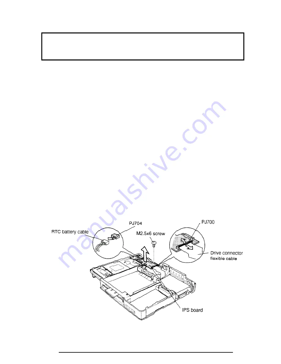
Disconnect the
RTC battery cable
from
PJ704
.
4.
Flip up the pressure connector to easily disconnect the
drive connector flexible
cable
from
PJ700
.
5.
Remove
one M2.5x6 screw
.
6.
Lift out the
IPS board
.
Figure 4-40 Removing the IPS board
Summary of Contents for Tecra 730CDT
Page 1: ...TOSHIBA 730CDT PN 730 9400 CATM 3970294 B01 ...
Page 6: ...vi 730CDT ...
Page 10: ...1 4 730CDT Figure 1 1 730CDT personal computer Figure 1 2 730CDT system unit configuration ...
Page 190: ...4 60 730CDT ...
Page 196: ...B 2 730CDT B 2 System Board Back View Figure B 2 System board layout back ...
Page 216: ...C 16 730CDT ...
Page 230: ...G 2 730CDT ...


