FIELD REPLACEABLE UNIT DOCUMENTATION
Tecra
TM
TOSHIBA
Tough Enough for Today’s World.
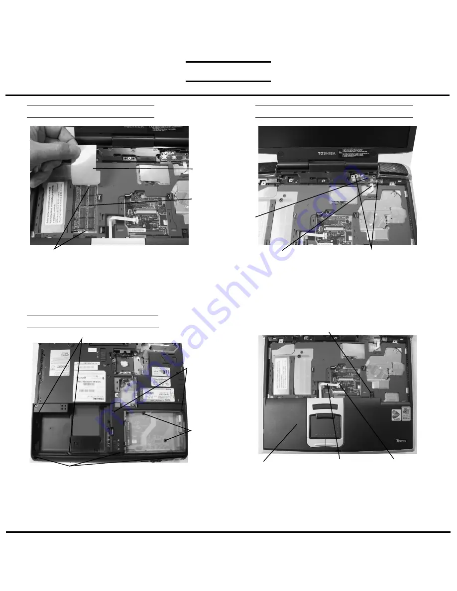
MEMORY MODULE REMOVAL
1. Lift up the
plastic insulator
covering the memory slots.
2. Spread the
memory clips
outward and pull the
memory
module
out of the connector on a 30 degree angle.
SENSOR/SWITCH BOARD REMOVAL
1. Remove
two M2.5x2.8 black flathead screws
securing the sensor switch board.
2. Disconnect the
sensor/switch board cable
from
PJ3200 on the back of the sensor/switch board.
2. Lift out the
sensor/switch board
.
PALM REST COVER REMOVAL
1. Turn the computer up side down.
2. Remove nine screws securing the palm rest cover:
-2 M2.5x4 black flat head screws
-3 M2.5x6 black flat head screws
-2 M2.5x10 black flat head screws
-2 M2.5x16 black flat head screws.
Memory
module
Memory clips
Plastic
insulator
M2.5x2.8 black flat head screws
Sensor/switch board cable
Sensor/
switch
board
M2.5x6 black flat head screw
M2.5x4 black flat head screws
M2.5x16
black`flat
head screws
M2.5x10
black flat
head screws
M2.5x4 black flat head screw
Touch pad cable
PJ2003
Palmrest cover
3.Turn the computer right side up and open the display
panel.
4. Disconnect the touch pad cable from PJ2003 on the
system board.
5. Remove
one M2.5x4 black flat head screw
securing
the palm rest cover.
6. Lift out the
palm rest cover
.
M1 Series


