MAINTENANCE MANUAL
103
STE 85357
5)
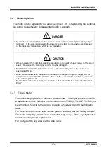
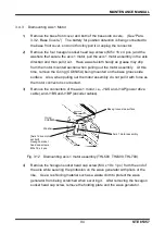
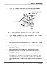
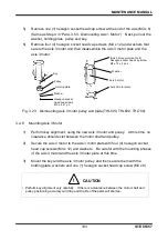
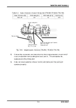
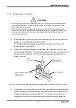
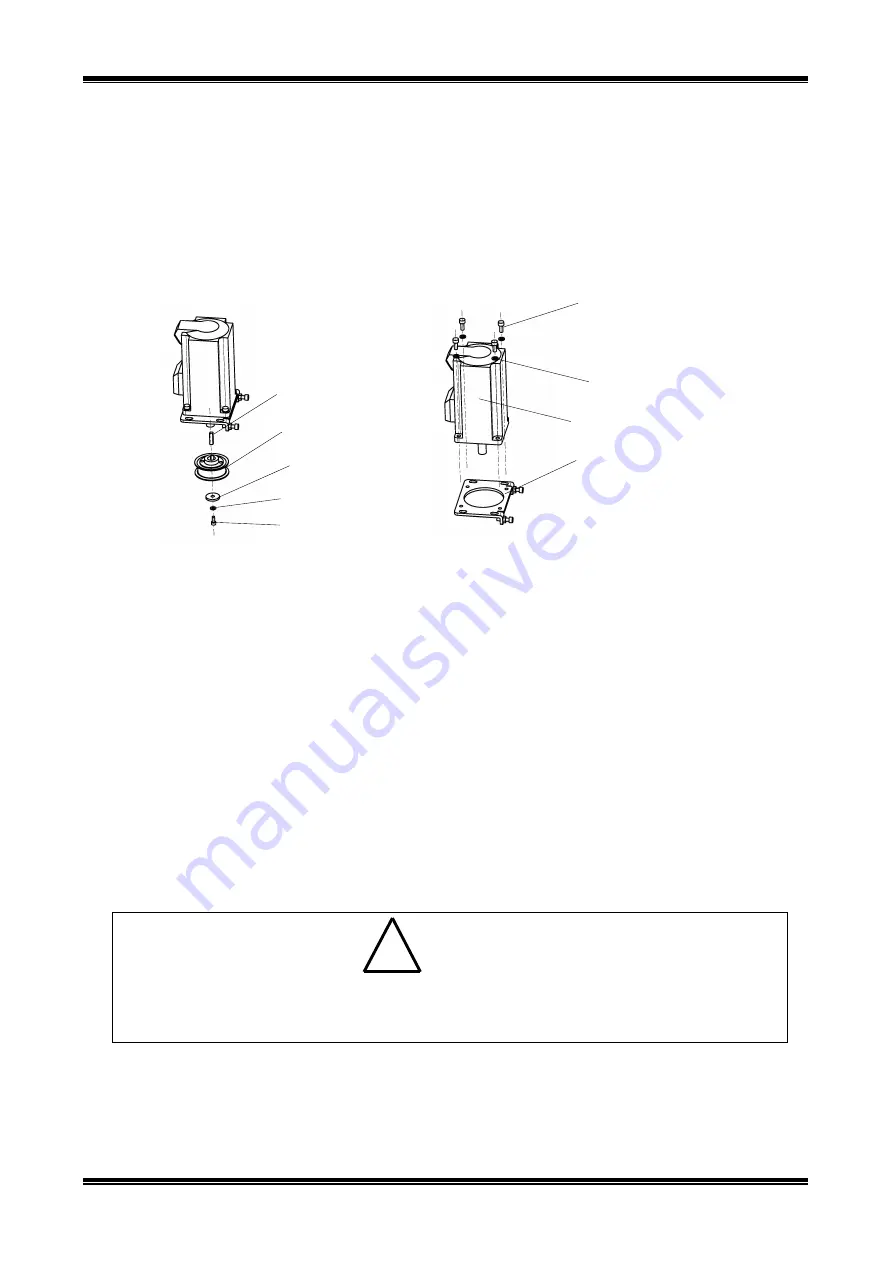
Remove one (1) hexagon socket head cap screw at the end of the axis (M3 x 8).
(Same as Step 4 in
“Para. 3.5.3, Dismounting Axis 1 Motor.”) Next, pull out the
washer, holding plate, pulley and key.
6)
Remove four (4) hexagon socket head cap screws (M4 x 12) and washers that
secure the axis 3 motor and then disassemble the axis 3 motor plate and the
axis 3 motor.
Fig. 3.23 Dismounting axis 3 motor pulley and plate (THL500, THL600, THL700)
3.4.8
Mounting Axis 3 Motor
1)
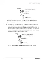
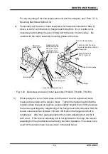
Perform key alignment, using the new axis 3 motor and pulley. At this time, no
clearance should exist between the motor shaft and pulley.
2)
Secure the axis 3 motor to the axis 3 motor plate with four (4) hexagon socket
head cap screws (M4 x 12) and washers. Be careful with the mounting phases
of the axis 3 motor and the axis 3 motor plate at this time.
3)
Mount the key and the axis 3 motor pulley, and then secure them with the
holding plate, washers and one (1) hexagon socket head cap screw (M3 x 8).
!
CAUTION
• Perform key alignment very carefully. If there is a clearance between the motor shaft and
pulley, positioning accuracy will drop and the life of the parts will shorten.
Washer
Holding plate
Pulley
Key
Hexagon socket
head cap screws
M3 x 8 x 1 pc.
[Axis 3 drive motor set bolt]
Hexagon socket head cap screw
M4 x 12 x 4 pcs.
Washer
Axis 3 motor plate
Axis 3 motor

