MAINTENANCE MANUAL
162
STE 85357
Ti
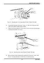
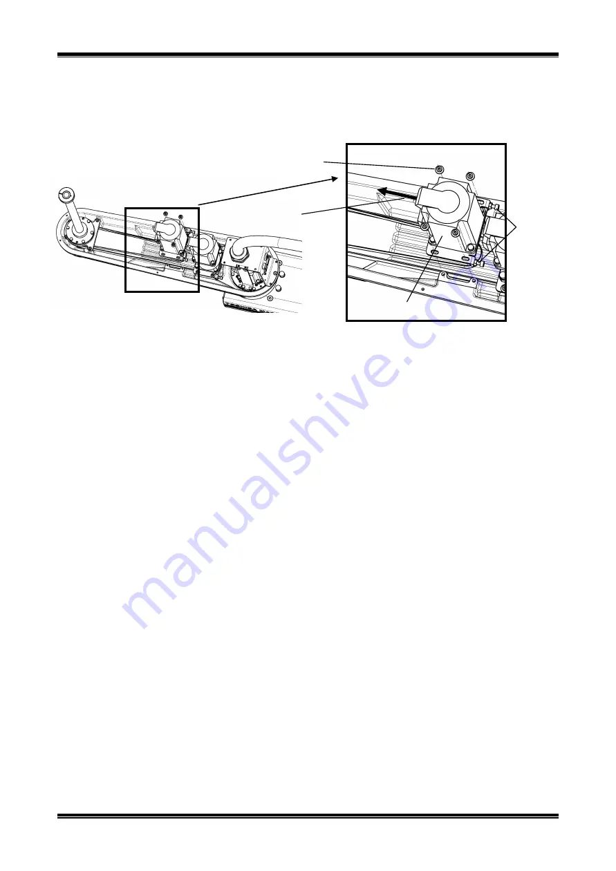
ming Belt.”) Then, tighten and secure the temporarily tightened flange head
bolts with hex nuts.
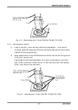
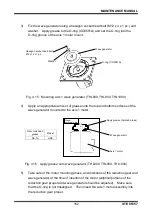
Fig. 4.30 Mounting axis 3 motor assembly (THL800, THL900, THL1000)
5)
Connect the connectors and set the cables back to the original state. (See the
pictures taken in Para. 4.4.7, Step 2.)
6)
Mount the arm 2 cover and perform home setting for Axes 3 and 4. Now, the
axis 3 motor replacement is complete.
7)
Carry out a test operation of Axes 3 and 4 and make sure that each part
operates properly.
4.4.9
Dismounting Axis 4 Motor
1)
Remove t
he arm 2 cover. (See “Para. 4.3.1, Arm 2 Cover.”)
2)
Cut the cable ties of the cables with nippers.
It is recommended to take photos of the cable installation positions and the
locations where cable ties are used so that these locations can be restored
when needed.
3)
Disconnect connectors J4AS and J4AP (power drive cables) and connectors
J4BS and J4BP (encoder cables) of the axis 4 motor.
4)
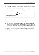
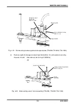
Remove the cap attached to the lateral side of the axis 4 reduction gear and
loosen the coupling bolt (M4) securing the axis 4 motor shaft and input shaft of
the axis 4 reduction gear.
If the hexagonal hole of the bolt is out of phase, adjust the phase by turning the
ball screw spline shaft by hand.
[Axis 3 motor plate mounting bolt]
Flange head bolt
M4 x 10 x 4 pcs.
Fasten so that the motor
lead wire faces the
direction of the arrow.
Bolts for adjusting
axis 3 tension
M4 x 16 x 2 pcs.
Hexagon nuts
Axis 3 motor assembly

