MAINTENANCE MANUAL
70
STE 85357
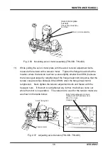
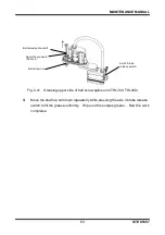
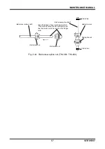
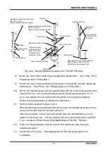
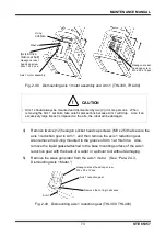
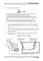
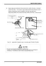
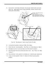
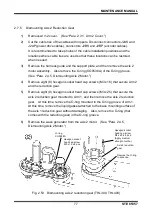
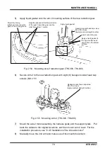
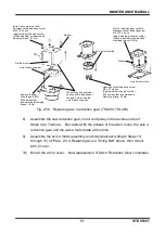
Fig. 2.46 Mounting ball screw spline nut (THL300, THL400)
8) Mount the axis 4 motor assembly and adjust the belt tension. (See "Para. 2.6.4,
Replacing Axis 4 Timing Belt.")
9)
Mount the axis 3 motor assembly and the axis 3 timing belt, and then adjust the
belt tension. (See "Para. 2.6.3, Replacing Axis 3 Timing Belt.")
10)
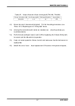
Mount the harness guide and the support plate with the cross recessed flat head
screw (M3 x 6 x 1 pc.) and the hexagon socket head cap screws (M3 x 6 x 2
pcs.), and restore the connectors and the cables to the original conditions.
(Refer to the photos taken in advance for reference.)
11)
Perform home setting for Axes 3 and 4.
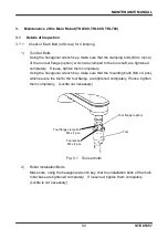
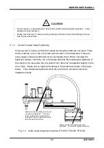
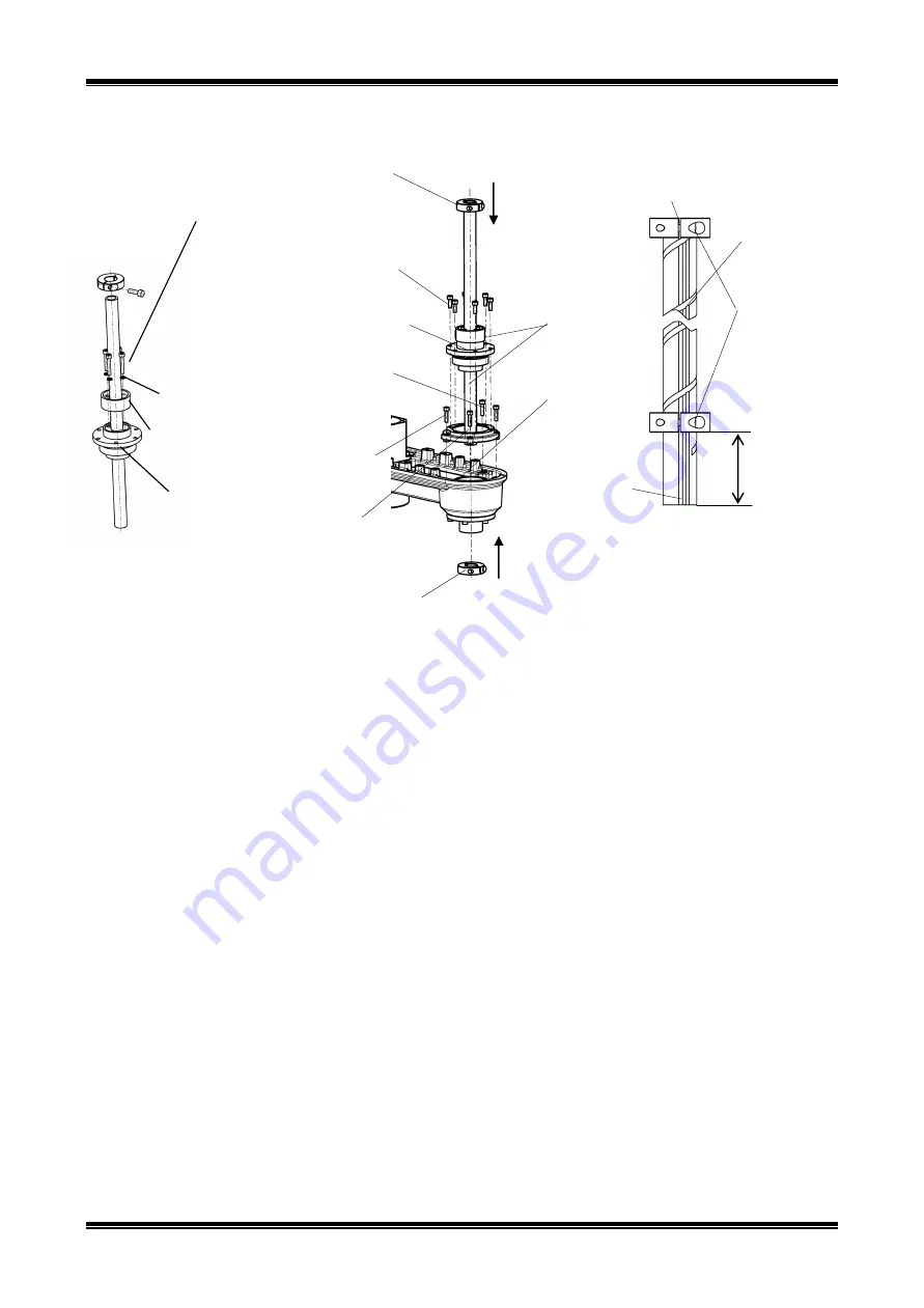
When performing home setting for the axis 4, align the stopper split line with the
home point match-mark on the ball spline nut.
After home setting, remove the mating mark from the old ball spline nut, and
attach it to the new one. For the location of home point match-mark, see Para.
7.4.4, Location of Robot Home Point Match-Marks (THL300, THL400).
12)
Carry out a test operation of Axes 3 and 4 and make sure that each part
operates properly.
13)
Mount the arm 2 cover. Now replacement of the ball screw spline unit
completes.
Washer
Pulley for the
axis 3 nut
27
Stopper
Stopper split line
Ball screw
groove
The bolt head
must be on the
right side.
Spline groove
Align each stopper split line with the
spline groove on the left of the
bottommost ball screw groove.
Stopper
Ball screw nut
Ball screw spline shaft
Ball screw nut
Axis 4 timing belt
Axis 3 bracket (casting)
Hexagon socket head cap screw
M4 x 12 x 6 pcs.
(Apply medium strength Loctite.)
Hexagon socket head cap screw
M4 x 25 x 4 pcs.
(Apply medium strength Loctite.)
Hexagon socket
head cap screw
M4 x 16 x 4 pcs.
(Apply medium
strength Loctite.)
Never remove.

