


Page 147
TMP86PM29BUG
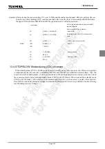
13.4 STOP/SLOW Modes during AD Conversion
When standby mode (STOP or SLOW mode) is entered forcibly during AD conversion, the AD convert operation
is suspended and the AD converter is initialized (ADCCR1 and ADCCR2 are initialized to initial value). Also, the
conversion result is indeterminate. (Conversion results up to the previous operation are cleared, so be sure to read
the conversion results before entering standby mode (STOP or SLOW mode).) When restored from standby mode
(STOP or SLOW mode), AD conversion is not automatically restarted, so it is necessary to restart AD conversion.
Note that since the analog reference voltage is automatically disconnected, there is no possibility of current flowing
into the analog reference voltage.
Example :After selecting the conversion time 19.5
µ
s at 16 MHz and the analog input channel AIN3 pin, perform AD con-
version once. After checking EOCF, read the converted value, store the lower 2 bits in address 0009EH nd store
the upper 8 bits in address 0009FH in RAM. The operation mode is software start mode.
: (port setting)
:
;Set port register approrriately before setting AD
converter registers.
:
:
(Refer to section I/O port in details)
LD
(ADCCR1) , 00100011B
; Select AIN3
LD
(ADCCR2) , 11011000B
;Select conversion time(312/fc) and operation
mode
SET
(ADCCR1) . 7
; ADRS = 1(AD conversion start)
SLOOP :
TEST
(ADCDR2) . 5
; EOCF= 1 ?
JRS
T, SLOOP
LD
A , (ADCDR2)
; Read result data
LD
(9EH) , A
LD
A , (ADCDR1)
; Read result data
LD
(9FH), A
Summary of Contents for TLCS-870/C Series
Page 1: ...8 Bit Microcontroller TLCS 870 C Series TMP86PM29BUG ...
Page 6: ...TMP86PM29BUG ...
Page 7: ...Revision History Date Revision 2007 10 11 1 First Release 2008 8 29 2 Contents Revised ...
Page 9: ......
Page 15: ...vi ...
Page 19: ...Page 4 1 3 Block Diagram TMP86PM29BUG 1 3 Block Diagram Figure 1 2 Block Diagram ...
Page 23: ...Page 8 1 4 Pin Names and Functions TMP86PM29BUG ...
Page 48: ...Page 33 TMP86PM29BUG ...
Page 49: ...Page 34 2 Operational Description 2 3 Reset Circuit TMP86PM29BUG ...
Page 61: ...Page 46 3 Interrupt Control Circuit 3 8 External Interrupts TMP86PM29BUG ...
Page 81: ...Page 66 6 Watchdog Timer WDT 6 3 Address Trap TMP86PM29BUG ...
Page 135: ...Page 120 10 8 Bit TimerCounter TC5 TC6 10 1 Configuration TMP86PM29BUG ...
Page 145: ...Page 130 11 Asynchronous Serial interface UART 11 9 Status Flag TMP86PM29BUG ...
Page 165: ...Page 150 13 10 bit AD Converter ADC 13 6 Precautions about AD Converter TMP86PM29BUG ...
Page 183: ...Page 168 15 LCD Driver 15 4 Control Method of LCD Driver TMP86PM29BUG ...
Page 201: ...Page 186 18 Electrical Characteristics 18 9 Handling Precaution TMP86PM29BUG ...
Page 203: ...Page 188 19 Package Dimensions TMP86PM29BUG ...
Page 205: ......


