TOSHIBA
TMPR3904F Rev. 2.0
135
26
transfer requests by the level detection of the DREQn signal and a edge mode that generates
transfer requests by the edge detection of the DREQn signal.
(4) Address modes
There are two address modes--a single address mode and a dual address mode.
The single address mode conducts the data transfer between a memory and an I/O device. The
memory is accessed by the address that the DMAC outputs and the I/O device is accessed
through the DACKn signal. This mode conducts reading from the source device and writing
into the destination device in one bus operation.
The dual address mode conducts the data transfer between memories or between a memory and
an I/O device. The addresses of the source device and the destination device are output by the
DMAC. When accessing the I/O device, the DMAC asserts the DACKn signal. This mode
implements the two bus operations--the read operation and the write operation. The transfer
data that were read out from the source device is temporarily taken in to the data holding register
(DHR) inside the DMAC and then is written into the destination device.
(5) Next transfer address can be set up (Continue mode)
In the single address mode, the next transfer starting address can be set up in the register in
advance (the continue mode). When the previous transfer has completed normally, the channel
being operated in the continue mode starts another data transfer, regarding the next transfer
address set up in the register as the transfer address of the new memory.
(6) Channel operations
DMAC0 has two channels (Channel 0 and Channel 1). The channel is turned on by setting the
start (Str) bit of the channel control register (CCRn) to 1; and it shall be in the wait status.
If a transfer request occurs when the channel is in the wait status, the DMAC is granted the bus
ownership to conduct the data transfer. When the transfer request is no longer there, the DMAC
releases the bus ownership to become the wait status. When the transfer completes, the channel
becomes the halt status. In the transfer completion, there are a normal completion and an
abnormal completion by causes such as an error occurrence. At the completion of a transfer, an
interrupt signal can be generated.
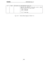
The following Figure 10-10 shows the outline of the status changes of the channel operations.
Summary of Contents for TMPR3904F
Page 1: ...Users Manual 32bit RISC Microprocessor TX39 family TMPR3904F Rev 2 0 Jan 12 1998 ...
Page 2: ......
Page 9: ...Users Manual 01 1 INTRODUCTION 1 1 Overview ...
Page 11: ...Users Manual 03 1 3 Kind of accessing by the TX3904 ...
Page 12: ...Users Manual 04 1 4 Precautions in the TMPR3904F specification Don t set Don t use ...
Page 13: ...Users Manual 05 Do not use ...
Page 14: ...Users Manual 06 ...
Page 15: ...Users Manual 7 2 FEATURES n n n n n n n n n n n n n ...
Page 16: ...Users Manual 8 ...
Page 18: ...Users Manual 10 ...
Page 19: ...Users Manual 11 4 PINS 4 1 Positions of Pins ...
Page 20: ...Users Manual 12 ...
Page 21: ...Users Manual 13 4 2 Functions of Pins ...
Page 22: ...Users Manual 14 ...
Page 23: ...Users Manual 15 ...
Page 24: ...Users Manual 16 ...
Page 26: ...Users Manual 18 5 2 Register Map ...
Page 27: ...Users Manual 19 ...
Page 28: ...Users Manual 20 ...
Page 30: ...Users Manual 22 5 3 2 PIO2 and PIO1 ...
Page 32: ...Users Manual 24 5 3 4 Connection of external bus master 5 3 5 INT 7 0 active status clear ...
Page 33: ...Users Manual 25 5 3 6 INT 7 0 active status set up ...
Page 34: ...Users Manual 26 ...
Page 123: ...TOSHIBA TMPR3904F Rev 2 0 115 26 ...
Page 169: ...TOSHIBA TMPR3904F Rev 2 0 161 26 ...
Page 203: ...TOSHIBA TMPR3904F Rev 2 0 195 ...
Page 230: ......

