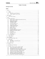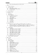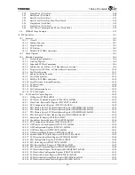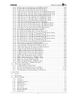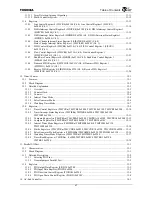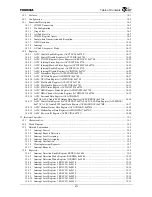
Table of Contents
vii
14.1
Features ........................................................................................................................................................ 14-1
14.2
Configuration ............................................................................................................................................... 14-2
14.3
Functional Description................................................................................................................................. 14-3
14.3.1
CODEC Connection ............................................................................................................................ 14-3
14.3.2
Pin Configuration ................................................................................................................................ 14-4
14.3.3
Usage Flow.......................................................................................................................................... 14-5
14.3.4
AC-link Start Up ................................................................................................................................. 14-7
14.3.5
CODEC Register Access ..................................................................................................................... 14-8
14.3.6
Sample-data Transmission and Reception........................................................................................... 14-9
14.3.7
GPIO Operation ................................................................................................................................ 14-14
14.3.8
Interrupt............................................................................................................................................. 14-15
14.3.9
AC-link Low-power Mode ................................................................................................................ 14-15
14.4
Registers..................................................................................................................................................... 14-16
14.4.1
ACLC Control Enable Register (ACCTLEN) 0xF700...................................................................... 14-17
14.4.2
ACLC Control Disable Register (ACCTLDIS) 0xF704 ................................................................... 14-20
14.4.3
ACLC CODEC Register Access Register (ACREGACC) 0xF708................................................... 14-22
14.4.4
ACLC Interrupt Status Register (ACINTSTS) 0xF710..................................................................... 14-23
14.4.5
ACLC Interrupt Masked Status Register (ACINTMSTS) 0xF714.................................................... 14-25
14.4.6
ACLC Interrupt Enable Register (ACINTEN) 0xF718..................................................................... 14-25
14.4.7
ACLC Interrupt Disable Register (ACINTDIS) 0xF71C.................................................................. 14-25
14.4.8
ACLC Semaphore Register (ACSEMAPH) 0xF720......................................................................... 14-26
14.4.9
ACLC GPI Data Register (ACGPIDAT) 0xF740.............................................................................. 14-27
14.4.10
ACLC GPO Data Register (ACGPODAT) 0xF744 .......................................................................... 14-28
14.4.11
ACLC Slot Enable Register (ACSLTEN) 0xF748 ............................................................................ 14-29
14.4.12
ACLC Slot Disable Register (ACSLTDIS) 0xF74C ......................................................................... 14-31
14.4.13
ACLC FIFO Status Register (ACFIFOSTS) 0xF750 ........................................................................ 14-32
14.4.14
ACLC DMA Request Status Register (ACDMASTS) 0xF780 ......................................................... 14-34
14.4.15
ACLC DMA Channel Selection Register (ACDMASEL) 0xF784 ................................................... 14-35
14.4.16
ACLC Surround Data Register (ACAUDODAT)
0xF7A0 ACLC Audio PCM Output Data Register (ACSURRDAT) 0xF7A4 .................................. 14-36
14.4.17
ACLC Center Data Register (ACCENTDAT) 0xF7A8 ACLC LFE Data Register (ACLFEDAT)
0xF7AC ACLC Audio PCM Input Data Register (ACMODODAT) 0xF7B8................................... 14-37
14.4.18
ACLC Modem Output Data Register (ACAUDIDAT) 0xF7B0 ....................................................... 14-38
14.4.19
ACLC Modem Input Data Register (ACMODIDAT) 0xF7BC......................................................... 14-39
14.4.20
ACLC Revision ID Register (ACREVID) 0xF7FC .......................................................................... 14-40
15.
Interrupt Controller ............................................................................................................................................... 15-1
15.1
Characteristics.............................................................................................................................................. 15-1
15.2
Block Diagram ............................................................................................................................................. 15-2
15.3
Detailed Explanation.................................................................................................................................... 15-4
15.3.1
Interrupt Sources ................................................................................................................................. 15-4
15.3.2
Interrupt Request Detection................................................................................................................. 15-5
15.3.3
Interrupt Level Assigning.................................................................................................................... 15-5
15.3.4
Interrupt Priority Assigning................................................................................................................. 15-5
15.3.5
Interrupt Notification........................................................................................................................... 15-6
15.3.6
Clearing Interrupt Requests................................................................................................................. 15-7
15.3.7
Interrupt Requests ............................................................................................................................... 15-7
15.4
Registers....................................................................................................................................................... 15-8
15.4.1
Interrupt Detection Enable Register (IRDEN) 0xF600 ....................................................................... 15-9
15.4.2
Interrupt Detection Mode Register 0 (IRDM0) 0xF604.................................................................... 15-10
15.4.3
Interrupt Detection Mode Register 1 (IRDM1) 0xF608.................................................................... 15-12
15.4.4
Interrupt Level Register 0 (IRLVL0) 0xF610 ................................................................................... 15-14
15.4.5
Interrupt Level Register 1 (IRLVL1) 0xF614 ................................................................................... 15-15
15.4.6
Interrupt Level Register 2 (IRLVL2) 0xF618 ................................................................................... 15-16
15.4.7
Interrupt Level Register 3 (IRLVL3) 0xF61C................................................................................... 15-17
15.4.8
Interrupt Level Register 4 (IRLVL4) 0xF620 ................................................................................... 15-18
15.4.9
Interrupt Level Register 5 (IRLVL5) 0xF624 ................................................................................... 15-19
15.4.10
Interrupt Level Register 6 (IRLVL6) 0xF628 ................................................................................... 15-20
15.4.11
Interrupt Level Register 7 (IRLVL7) 0xF62C................................................................................... 15-21
Summary of Contents for TMPR4925
Page 1: ...64 Bit TX System RISC TX49 Family TMPR4925 Rev 3 0 ...
Page 4: ......
Page 15: ...Handling Precautions ...
Page 16: ......
Page 18: ...1 Using Toshiba Semiconductors Safely 1 2 ...
Page 40: ...3 General Safety Precautions and Usage Considerations 3 18 ...
Page 42: ...4 Precautions and Usage Considerations 4 2 ...
Page 43: ...TMPR4925 ...
Page 44: ......
Page 54: ...Chapter 1 Features 1 8 ...
Page 58: ...Chapter 2 Block Diagram 2 4 ...
Page 88: ...Chapter 4 Address Mapping 4 12 ...
Page 226: ...Chapter 8 DMA Controller 8 58 ...
Page 260: ...Chapter 9 SDRAM Controller 9 34 ...
Page 480: ...Chapter 15 Interrupt Controller 15 32 ...
Page 554: ...Chapter 19 Real Time Clock RTC 19 8 ...
Page 555: ...Chapter 20 Removed 20 1 20 Removed ...
Page 556: ...Chapter 20 Removed 20 2 ...
Page 564: ...Chapter 21 Extended EJTAG Interface 21 8 ...
Page 580: ...Chapter 22 Electrical Characteristics 22 16 ...
Page 588: ...Chapter 24 Usage Notes 24 2 ...


