Chapter 8 DMA Controller
8-4
8.3.3
External I/O DMA Transfer Mode
The External I/O DMA Transfer Mode performs DMA transfer with external I/O devices that are
connected to the External Bus Controller.
8.3.3.1 External
Interface
External I/O devices signal DMA requests to the DMA Controller by asserting the DMA
Transfer Request Signal (DMAREQ[n]). On the other hand, the DMA Controller accesses external
I/O devices by asserting the DMA Transfer Acknowledge Signal (DMAACK[n]).
The DMA Transfer Request signal (DMAREQ[n]) can use the Request Polarity bit (REQPOL)
of the DMA Channel Control Register (DMCCRn) to select the signal polarity for each channel,
and can use the Edge Request bit (EGREQ) to select either edge detection or level detection for
each channel. The DMA Transfer Acknowledge signal (DMAACK[n]) can also use the
Acknowledge Polarity bit (ACKPOL) to select the polarity.
Please assert/deassert the DMAREQ[n] signal as follows below.
•
When level detection is set (DMCCRn.EGREQ = 0)
The DMAREQ[n] signal must be continuously asserted until one SYSCLK cycle after the
DMAACK[n] signal is asserted. Also, the DMAREQ[n] signal must be asserted before the
CE*/CS* signal is deasserted. If this signal is asserted too soon, DMA transfer will not be
performed. If this signal is asserted too late, unexpected DMA transfer may result.
During Dual Address transfer, we recommend detecting assertion of the CE* signal for the
external I/O device that is currently asserting DMAACK[n], then deasserting DMAREQ[n].
•
When edge detection is set (DMCCRn.EGREQ
=
1)
Please set up assertion of the DMAREQ[n] signal so the DMAREQ[n] signal is asserted
after the DMAACK[n] signal corresponding to a previously asserted DMAREQ[n] signal is
deasserted. The DMAREQ[n] signal will not be detected even if it is asserted before
DMAACK[n] is deasserted.
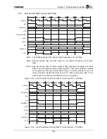
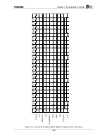
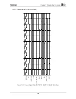
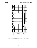
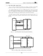
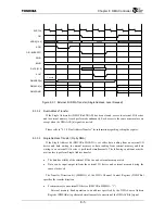
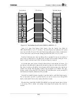
Figure 8.3.1 is a timing diagram that shows the timing of external DMA access. In this timing
diagram, both the DMAREQ[n] signal and the DMAACK[n] signal are set to Low active
(DMCCRn.REQPL = 0, DMCCRn.ACKPOL = 0).
The DMAACK[n] and DMADONE signals, which are DMA control signals, are synchronized
to SDCLK. When these signals are used by an external I/O device that is synchronous to
SYSCLK, it is necessary to take clock skew into account.
The DMAACK[n] signal is asserted either at the SYSCLK cycle, the same as with assertion of
the CE*/CS* signal, or before that. In addition, it is deasserted after the last ACK*/READY signal
is deasserted.
When the DMADONE* signal (refer to 8.3.3.4) is used as an output signal, it is asserted for at
least one SYSCLK cycle while the DMAACK[n] signal is asserted either during the same
SYSCLK cycle that the CE*/CS* signal is deasserted or during a subsequent SYSCLK cycle.
When the DMADONE* signal is used as an input signal, it must be asserted for one SYSCLK
cycle while the DMAACK[n] signal is being asserted.
Summary of Contents for TMPR4925
Page 1: ...64 Bit TX System RISC TX49 Family TMPR4925 Rev 3 0 ...
Page 4: ......
Page 15: ...Handling Precautions ...
Page 16: ......
Page 18: ...1 Using Toshiba Semiconductors Safely 1 2 ...
Page 40: ...3 General Safety Precautions and Usage Considerations 3 18 ...
Page 42: ...4 Precautions and Usage Considerations 4 2 ...
Page 43: ...TMPR4925 ...
Page 44: ......
Page 54: ...Chapter 1 Features 1 8 ...
Page 58: ...Chapter 2 Block Diagram 2 4 ...
Page 88: ...Chapter 4 Address Mapping 4 12 ...
Page 226: ...Chapter 8 DMA Controller 8 58 ...
Page 260: ...Chapter 9 SDRAM Controller 9 34 ...
Page 480: ...Chapter 15 Interrupt Controller 15 32 ...
Page 554: ...Chapter 19 Real Time Clock RTC 19 8 ...
Page 555: ...Chapter 20 Removed 20 1 20 Removed ...
Page 556: ...Chapter 20 Removed 20 2 ...
Page 564: ...Chapter 21 Extended EJTAG Interface 21 8 ...
Page 580: ...Chapter 22 Electrical Characteristics 22 16 ...
Page 588: ...Chapter 24 Usage Notes 24 2 ...


