Chapter 8 DMA Controller
8-24
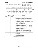
8.4.2
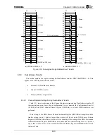
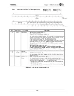
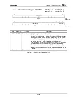
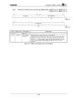
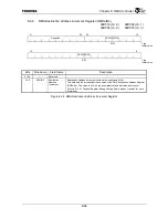
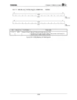
DMA Channel Control Register (DMCCRn)
0xB018 (ch. 0)
0xB038 (ch. 1)
0xB058 (ch. 2)
0xB078 (ch. 3)
31 30 29 28 27 26 25 24 23 22 21 20 19 18 17 16
Reserved
IMMCHN
USEXFSZ
LE
DBINH SBINH CHRST
RVBYTE ACKPOL
REQPL EGREQ CHDN
DNCTL
EXTRQ
R/W R/W R/W R/W R/W R/W R/W R/W R/W R/W R/W
R/W
R/W
:
Type
0 0 - 0 0 1 0 0 0 0 0
00
0
:
Initial
value
15 13
12
11
10 9 8 7 6 5 4 2 1 0
STLTIME/INTRQD
INTENE INTENC
INTENT
CHNEN XFACT
Reserved
SMPCHN
XFSZ
MEMIO
SNGAD
R/W R/W
R/W
R/W R R/W R/W R/W R/W R/W
R/W
:
Type
000 0 0 0 0 0
00
0 000 0 0
:
Initial
value
Bit Mnemonic
Field
Name
Description
31:30
⎯
Reserved
⎯
29
IMMCHN
Immediate Chain
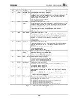
Immediate Chain (Initial value: 0, R/W)
Selects the control method of bus ownership during chain transfer.
1: When the DMA transfer completes due to the current DMA Channel Register and
DMCCRn.CHNEN=1, DMA Command Descriptor of the address set in DMCHARn
is loaded to DMA channel Register without bus ownership release. (Chain
Transfer)
0: When the DMA transfer completes due to the current DMA Channel Register and
DMCCRn.CHNEN=1, DMA controller once releases the bus ownership. After that
it gets bus ownership again and starts Chain Transfer.
Note: It is not concerned with the setup of this bit but DMA controller releases bus
ownership after the Chain Transfer ends.
28 USEXFSZ
Transfer Set Size
Mode
Use Transfer Set Size (Initial value: 0, R/W)
Selects the DMA channel operation mode during Burst DMA transfer. Refer to
“8.3.7.2 Burst Transfer During Single Address Transfer” and “8.3.8.2 Burst Transfer
During Dual Address Transfer” for more information.
1: The DMA Controller always transfers the amount of data set in DMCCRn.XFSZ for
each bus operation. Since alignment to the boundary of the DMCCRn.XFSZ in the
address is not forced when in this mode, transfers that exceed 32 -word
boundaries are divided into two operations.
0: The DMA Controller calculates the transfer size so the address set in DMSARn
and DMDARn (only during Dual Address transfer) can be aligned to the boundary
of the size set in DMCCRn.XFSZ, then transfers data according to that size.
Note: During dual address transfer, "0" becomes effective only when MSARn and
DMDARn are aligned on a word boundary, and the value of DMCNTRn is a
multiple of 4-byte.
27 LE
Little
Endian
Little Endian (Initial value: value that is the opposite of the G-Bus Endian
(CCFG.ENDIAN), R/W)
This bit sets the Endian of the channel. Use the initial value.
1: Channel operates in the Little Endian mode
0: Channel operates in the Big Endian mode
Figure 8.4.2 DMA Channel Control Register (1/4)
Summary of Contents for TMPR4925
Page 1: ...64 Bit TX System RISC TX49 Family TMPR4925 Rev 3 0 ...
Page 4: ......
Page 15: ...Handling Precautions ...
Page 16: ......
Page 18: ...1 Using Toshiba Semiconductors Safely 1 2 ...
Page 40: ...3 General Safety Precautions and Usage Considerations 3 18 ...
Page 42: ...4 Precautions and Usage Considerations 4 2 ...
Page 43: ...TMPR4925 ...
Page 44: ......
Page 54: ...Chapter 1 Features 1 8 ...
Page 58: ...Chapter 2 Block Diagram 2 4 ...
Page 88: ...Chapter 4 Address Mapping 4 12 ...
Page 226: ...Chapter 8 DMA Controller 8 58 ...
Page 260: ...Chapter 9 SDRAM Controller 9 34 ...
Page 480: ...Chapter 15 Interrupt Controller 15 32 ...
Page 554: ...Chapter 19 Real Time Clock RTC 19 8 ...
Page 555: ...Chapter 20 Removed 20 1 20 Removed ...
Page 556: ...Chapter 20 Removed 20 2 ...
Page 564: ...Chapter 21 Extended EJTAG Interface 21 8 ...
Page 580: ...Chapter 22 Electrical Characteristics 22 16 ...
Page 588: ...Chapter 24 Usage Notes 24 2 ...

