2 Safety Precautions
2-2
2.1
General Precautions regarding Semiconductor Devices
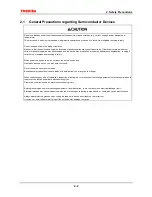
Do not use devices under conditions exceeding their absolute maximum ratings (e.g. current, voltage, power dissipation or
temperature).
This may cause the device to break down, degrade its performance, or cause it to catch fire or explode resulting in injury.
Do not insert devices in the wrong orientation.
Make sure that the positive and negative terminals of power supplies are connected correctly. Otherwise the rated maximum
current or power dissipation may be exceeded and the device may break down or undergo performance degradation, causing it
to catch fire or explode and resulting in injury.
When power to a device is on, do not touch the device’s heat sink.
Heat sinks become hot, so you may burn your hand.
Do not touch the tips of device leads.
Because some types of device have leads with pointed tips, you may prick your finger.
When conducting any kind of evaluation, inspection or testing, be sure to connect the testing equipment’s electrodes or probes to
the pins of the device under test before powering it on.
Otherwise, you may receive an electric shock causing injury.
Before grounding an item of measuring equipment or a soldering iron, check that there is no electrical leakage from it.
Electrical leakage may cause the device which you are testing or soldering to break down, or could give you an electric shock.
Always wear protective glasses when cutting the leads of a device with clippers or a similar tool.
If you do not, small bits of metal flying off the cut ends may damage your eyes.
Summary of Contents for TMPR4925
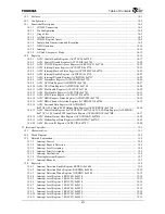
Page 1: ...64 Bit TX System RISC TX49 Family TMPR4925 Rev 3 0 ...
Page 4: ......
Page 15: ...Handling Precautions ...
Page 16: ......
Page 18: ...1 Using Toshiba Semiconductors Safely 1 2 ...
Page 40: ...3 General Safety Precautions and Usage Considerations 3 18 ...
Page 42: ...4 Precautions and Usage Considerations 4 2 ...
Page 43: ...TMPR4925 ...
Page 44: ......
Page 54: ...Chapter 1 Features 1 8 ...
Page 58: ...Chapter 2 Block Diagram 2 4 ...
Page 88: ...Chapter 4 Address Mapping 4 12 ...
Page 226: ...Chapter 8 DMA Controller 8 58 ...
Page 260: ...Chapter 9 SDRAM Controller 9 34 ...
Page 480: ...Chapter 15 Interrupt Controller 15 32 ...
Page 554: ...Chapter 19 Real Time Clock RTC 19 8 ...
Page 555: ...Chapter 20 Removed 20 1 20 Removed ...
Page 556: ...Chapter 20 Removed 20 2 ...
Page 564: ...Chapter 21 Extended EJTAG Interface 21 8 ...
Page 580: ...Chapter 22 Electrical Characteristics 22 16 ...
Page 588: ...Chapter 24 Usage Notes 24 2 ...

