Chapter 10 PCI Controller
10-21
10.3.11.2 Priority Control
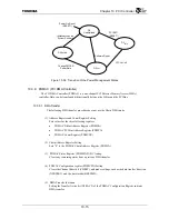
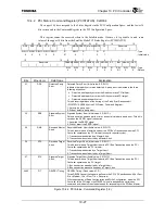
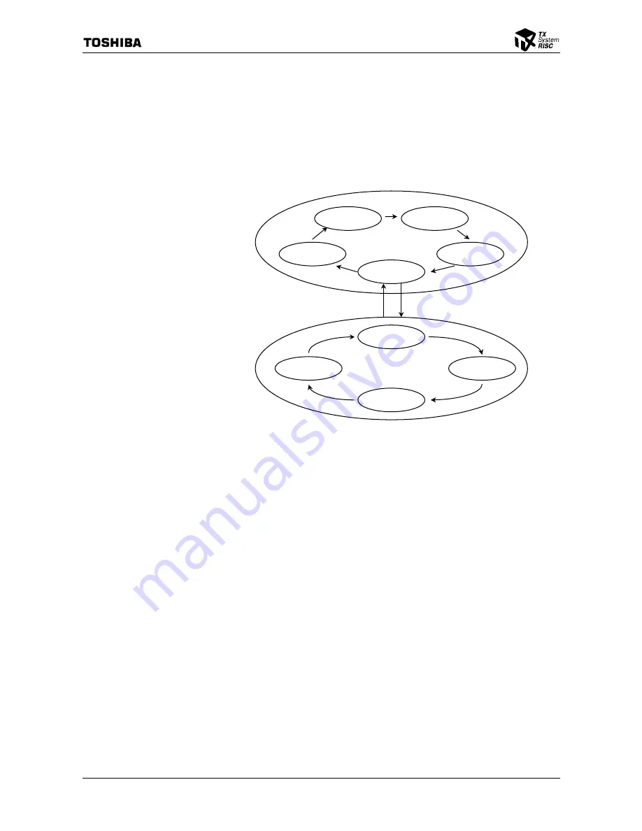
As illustrated below in Figure 10.3.9, a combination of two round-robin sequences is used as
the arbitration algorithm that determines the priority of Internal PCI Bus arbiter bus requests. The
round-robin with the lower priority (Level 2) consists of Masters W - Z, and the round-robin with
the high priority (Level 1), consists of Master A - D and Level 2 Masters. The PCI Bus Arbiter
Request Port Register (PBAREQPORT) specifies whether to allocate the PCI Controller and the
four External Bus Masters to Masters A-D or W - Z.
Figure 10.3.9 PCI Bus Arbitration Priority
The Bus Master priority is determined based on the Level 1 round-robin sequence. However,
when Level 2 is used inside Level 1, the Level 2 Bus Master priority is determined based on the
Level 2 round-robin sequence.
All 8 Bus Masters cannot be used on the TX4925. However, the Bus Master priority would be
as follows if we assume there is a hypothetical device that can use all 8 Bus Masters and all 8 Bus
Masters (Masters A – D, W – Z) simultaneously requested the bus.
A
→
B
→
C
→
D
→
W
→
A
→
B
→
C
→
D
→
X
→
A
→
B
→
C
→
D
→
Y
→
A
→
B
→
C
→
D
→
Z
→
A (returns to the beginning)
Since the priority can only transition in the order indicated by the above arrows (or the arrows
in Figure 10.3.9, if we assume that the three Bus Masters A, B, and W exist, then Master B will
obtain the bus first. If A and W then simultaneously request the bus, then PCI Bus ownership will
transition in the order B
→
W
→
A.
Level 2
(Priority: Low)
Level 1
(Prirority: High)
Master A
Level 2
Master Z
Master X
Master W
Master B
Master C
Master D
Master Y
Summary of Contents for TMPR4925
Page 1: ...64 Bit TX System RISC TX49 Family TMPR4925 Rev 3 0 ...
Page 4: ......
Page 15: ...Handling Precautions ...
Page 16: ......
Page 18: ...1 Using Toshiba Semiconductors Safely 1 2 ...
Page 40: ...3 General Safety Precautions and Usage Considerations 3 18 ...
Page 42: ...4 Precautions and Usage Considerations 4 2 ...
Page 43: ...TMPR4925 ...
Page 44: ......
Page 54: ...Chapter 1 Features 1 8 ...
Page 58: ...Chapter 2 Block Diagram 2 4 ...
Page 88: ...Chapter 4 Address Mapping 4 12 ...
Page 226: ...Chapter 8 DMA Controller 8 58 ...
Page 260: ...Chapter 9 SDRAM Controller 9 34 ...
Page 480: ...Chapter 15 Interrupt Controller 15 32 ...
Page 554: ...Chapter 19 Real Time Clock RTC 19 8 ...
Page 555: ...Chapter 20 Removed 20 1 20 Removed ...
Page 556: ...Chapter 20 Removed 20 2 ...
Page 564: ...Chapter 21 Extended EJTAG Interface 21 8 ...
Page 580: ...Chapter 22 Electrical Characteristics 22 16 ...
Page 588: ...Chapter 24 Usage Notes 24 2 ...

