Chapter 10 PCI Controller
10-27
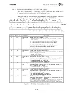
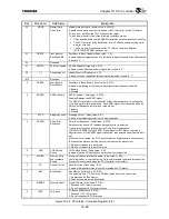
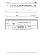
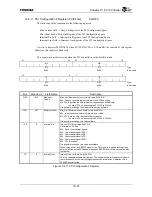
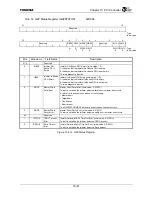
10.4.2 PCI Status, Command Register (PCISTATUS) 0xD004
The upper 16 bits correspond to the Status Register in the PCI Configuration Space, and the lower 16
bits correspond to the Command Register in the PCI Configuration Space.
This register cannot be accessed when in the Satellite mode. However, it is possible to read some
values of the upper 16 bits from the Satellite Mode PCI Status Register (PCISSTATUS).
31 30 29 28 27 26 25 24 23 22 21 20 19
16
DPE SSE RMA RTA STA
DT
MDPE FBBCP
Reserved
66MCP
CL Reserved
R/W1C
R/W1C
R/W1C
R/W1C R/W1C R R/W1C
R R
R
:
Type
0 0 0 0 0
01
0 1 0 1
:
Initial
value
15 10 9 8 7 6 5 4 3 2 1 0
Reserved FBBEN SEREN STPC PEREN VPS
MWIEN
SC
BM
MEMSP
IOSP
R/W
R/W R R/W R R/W R R/W
R/W
R/W
:
Type
0 0 0 0 0 0 0 0/1 0 0
:
Default
Bits Mnemonic Field
Name
Explanation
31 DPE
Detected Parity
Error
Detected Parity Error (Initial value: 0, R/W1C)
Indicates that a parity error was detected. A parity error is detected in the three
following situations:
•
Detected a data parity error as the Read command PCI initiator.
•
Detected a data parity error as the Write command PCI target.
•
Detected an address parity error.
This bit is set regardless of the setting of the Parity Error Response bit
(PCISTATUS.PEREN) of the PCI Status, Command Register.
1: Detected a parity error.
0: Did not detect a parity error.
30 SSE
Signaled System
Error
Signaled System Error (Initial value: 0, R/W1C)
Detects either an address parity error or a special cycle data parity error. This bit is
set when the SERR
*
signal is asserted.
1: Asserted the SERR
*
signal
0: Did not assert the SERR
*
signal.
29 RMA
Received Master
Abort
Received Master Abort (Initial value: 0, R/W1C)
This bit is set when a Master Abort aborts a PCI Bus Transaction when the PCI
Controller operates as the PCI initiator (except for special cycles).
1: Transaction was aborted by a Master Abort.
0: Transaction was not aborted by a Master Abort.
28 RTA
Received Target
Abort
Received Target Abort (Initial value: 0, R/W1C)
This bit is set when a Target Abort aborts a PCI Bus Transaction when the PCI
Controller operates as the PCI initiator.
1: Transaction was aborted by a Target Abort.
0: Transaction was not aborted by a Target Abort.
27 STA
Signaled Target
Abort
Signaled Target Abort (Initial value: 0, R/W1C)
This bit is set when a Target Abort aborts a PCI Bus Transaction when the PCI
Controller operates as the PCI target.
1: Bus transaction was aborted by a Target Abort.
0: Bus transaction was not aborted by a Target Abort.
26:25
DT
DEVSEL Timing
DEVSEL Timing (Fixed value: 01, R)
Three DEVSEL assert timings are defined in the PCI 2.2 Specifications: 00b = Fast;
01b = Medium; 10b = Slow; 11b = Reserved).
With the exception of Read Configuration and Write Configuration, when the PCI
Controller is the PCI target, the DEVSEL signal is asserted to a certain bus
command and indicates the slowest speed for responding to the PCI Bus Master.
Figure 10.4.2 PCI Status, Command Register (1/2)
Summary of Contents for TMPR4925
Page 1: ...64 Bit TX System RISC TX49 Family TMPR4925 Rev 3 0 ...
Page 4: ......
Page 15: ...Handling Precautions ...
Page 16: ......
Page 18: ...1 Using Toshiba Semiconductors Safely 1 2 ...
Page 40: ...3 General Safety Precautions and Usage Considerations 3 18 ...
Page 42: ...4 Precautions and Usage Considerations 4 2 ...
Page 43: ...TMPR4925 ...
Page 44: ......
Page 54: ...Chapter 1 Features 1 8 ...
Page 58: ...Chapter 2 Block Diagram 2 4 ...
Page 88: ...Chapter 4 Address Mapping 4 12 ...
Page 226: ...Chapter 8 DMA Controller 8 58 ...
Page 260: ...Chapter 9 SDRAM Controller 9 34 ...
Page 480: ...Chapter 15 Interrupt Controller 15 32 ...
Page 554: ...Chapter 19 Real Time Clock RTC 19 8 ...
Page 555: ...Chapter 20 Removed 20 1 20 Removed ...
Page 556: ...Chapter 20 Removed 20 2 ...
Page 564: ...Chapter 21 Extended EJTAG Interface 21 8 ...
Page 580: ...Chapter 22 Electrical Characteristics 22 16 ...
Page 588: ...Chapter 24 Usage Notes 24 2 ...


