Chapter 10 PCI Controller
10-97
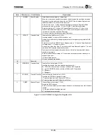
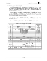
Bits Mnemonic Field
Name
Description
6:5
⎯
Reserved
⎯
4
PCIPERR
PCI Parity Error
PCI Parity Error (Initial value: 0, R/W1C)
1: Indicates that there was a parity error on a PCI transaction performed on behalf of
the
PDMAC.
0: Indicates that no parity error has been detected on PDMAC PCI transfer since this
bit was cleared.
3
PCISERR
PCI System Error PCI System Error (Initial value: 0, R/W1C)
1: Indicates that a PCI bus module asserted SERR
*
during a PCI operation initiated
by the PDMAC.
0: Indicates that SERR
*
has not been asserted during a PDMAC-initiated PCI cycle
since this bit was last cleared.
2
PCIERR
PCI Fatal Error
PCI Fatal Error (Initial value: 0, R/W1C)
1: Indicates that an error was signaled on the PCI Bus during a PCI operation initiated
by the PDMAC.
0: Indicates that no error has been signaled on the PCI Bus since this bit was
previously
cleared.
1 CHNERR
G-Bus Chain
Error
G-Bus Chain Bus Error (Initial value: 0, R/W1C)
1: Indicates that a G-Bus error occurred during the Chain process. DMA transfer
stops.
0: Indicates that no G-Bus error has occurred during the Chain process since this bit
was
cleared.
0
DATAERR
G-Bus Data Error G-Bus Data Bus Error (Initial value: 0, R/W1C)
1: Indicates that a G-Bus error occurred during the data transfer process. DMA
transfer
stops.
0: Indicates that no G-Bus error has occurred during the data transfer process since
this bit was cleared.
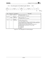
Figure 10.4.66 PDMAC Status Register (2/2)
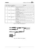
Figure 10.4.67 PDMAC Interrupt Signaling
DONEINT
PCISERR
PCIERR
CHNERR
DATAERR
PCIPERR
ERRINT
ERRIE
NCCMP
NCCMPIE
NTCMP
NTCMPIE
Interrupt Controller
(Interrupt No. 15)
ACCMP
Summary of Contents for TMPR4925
Page 1: ...64 Bit TX System RISC TX49 Family TMPR4925 Rev 3 0 ...
Page 4: ......
Page 15: ...Handling Precautions ...
Page 16: ......
Page 18: ...1 Using Toshiba Semiconductors Safely 1 2 ...
Page 40: ...3 General Safety Precautions and Usage Considerations 3 18 ...
Page 42: ...4 Precautions and Usage Considerations 4 2 ...
Page 43: ...TMPR4925 ...
Page 44: ......
Page 54: ...Chapter 1 Features 1 8 ...
Page 58: ...Chapter 2 Block Diagram 2 4 ...
Page 88: ...Chapter 4 Address Mapping 4 12 ...
Page 226: ...Chapter 8 DMA Controller 8 58 ...
Page 260: ...Chapter 9 SDRAM Controller 9 34 ...
Page 480: ...Chapter 15 Interrupt Controller 15 32 ...
Page 554: ...Chapter 19 Real Time Clock RTC 19 8 ...
Page 555: ...Chapter 20 Removed 20 1 20 Removed ...
Page 556: ...Chapter 20 Removed 20 2 ...
Page 564: ...Chapter 21 Extended EJTAG Interface 21 8 ...
Page 580: ...Chapter 22 Electrical Characteristics 22 16 ...
Page 588: ...Chapter 24 Usage Notes 24 2 ...

