Chapter 10 PCI Controller
10-101
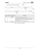
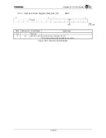
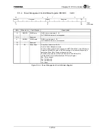
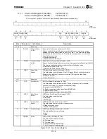
10.5.3 Power Management Capability Register (PMC)
0xDE
15 11
10 9 8 6 5 4 3 2 0
PMESPT D2SPT
D1SPT
Reserved
DSI
Reserved PMECLK
PMVER
R R R R R R
:
Type
0x00
0 0 0 0
0x2
:
Initial
value
Bits Mnemonic Field
Name
Description
15:11 PMESPT
PME Output
Support
PME_ Support (Fixed value: 0x00, R)
On TX4925 the function is not supported.
10
D2SPT
D2 Support
D2_Support (Fixed value: 0, R)
0: Indicates that the D2 state is not supported.
9
D1SPT
D1 Support
D1_Support (Fixed value: 0, R)
0: Indicates that the D1 state is not supported.
8:6
⎯
Reserved
⎯
5
DSI
DSI
DSI (Fixed value: 0, R)
1: Indicates that Device Specific Initialization is required.
4
⎯
Reserved
⎯
3
PMECLK
PME Clock
PME Clock (Fixed value: 0, R)
0: Indicates that the PCI Clock is not required to assert the PME
*
signal.
2:0 PMVER
Power
Management I/F
Version
Version (Fixed value: 0x2, R)
2: Indicates compliance with “PCI Power Management Interface Specification”
Version
1.1.
Figure 10.5.3 Power Management Capability Register
Summary of Contents for TMPR4925
Page 1: ...64 Bit TX System RISC TX49 Family TMPR4925 Rev 3 0 ...
Page 4: ......
Page 15: ...Handling Precautions ...
Page 16: ......
Page 18: ...1 Using Toshiba Semiconductors Safely 1 2 ...
Page 40: ...3 General Safety Precautions and Usage Considerations 3 18 ...
Page 42: ...4 Precautions and Usage Considerations 4 2 ...
Page 43: ...TMPR4925 ...
Page 44: ......
Page 54: ...Chapter 1 Features 1 8 ...
Page 58: ...Chapter 2 Block Diagram 2 4 ...
Page 88: ...Chapter 4 Address Mapping 4 12 ...
Page 226: ...Chapter 8 DMA Controller 8 58 ...
Page 260: ...Chapter 9 SDRAM Controller 9 34 ...
Page 480: ...Chapter 15 Interrupt Controller 15 32 ...
Page 554: ...Chapter 19 Real Time Clock RTC 19 8 ...
Page 555: ...Chapter 20 Removed 20 1 20 Removed ...
Page 556: ...Chapter 20 Removed 20 2 ...
Page 564: ...Chapter 21 Extended EJTAG Interface 21 8 ...
Page 580: ...Chapter 22 Electrical Characteristics 22 16 ...
Page 588: ...Chapter 24 Usage Notes 24 2 ...


