Chapter 12 Timer/Counter
12-4
12.3.3 Counter
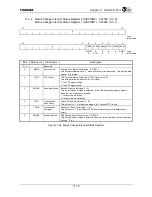
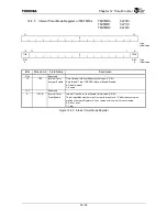
Each channel has an independent 32-bit counter. Set the Timer Count Enable bit (TMTCRn.TCE) and
the 32-bit counter will start counting.
Clear the Timer Count Enable bit to stop the counter. If the Counter Reset Enable bit
(TMTCRn.CRE) is set, then the counter will be cleared also. The Watchdog Timer Disable bit
(TMWTRM2.WDIS) must be set in order to stop and clear this counter when in the Watch Dog Timer
mode.
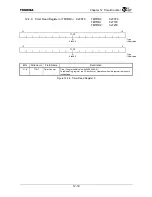
Also, reading the Timer Read Register (TMTRR) makes it possible to fetch the counter value.
12.3.4 Interval
Timer
Mode
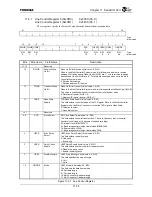
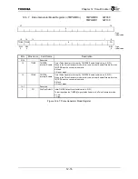
The Interval Timer mode is used to periodically generate interrupts. Setting the Timer Mode field
(TMTCRn.TMODE) of the Timer Control Register to “00” sets the timer to the Interval Timer mode.
This mode can be used by all timers.
When the count value matches the value of Compare Register A (TMCPRAn), the Interval Timer
TMCPRA Status bit (TMTISRn.TIIS) of the Timer Interrupt Status Register is set. When the Interval
Timer Interrupt Enable bit (TMITMRn.TIIE) of the Interval Timer Mode Register is set, timer interrupts
occur. When a “0” is written to the Interval Timer TMCPRA Status bit (TMTISRn.TIIS), TIIS is cleared
and timer interrupts stop.
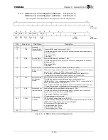
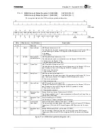
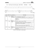
If the Timer Zero Clear Enable bit (TMITMRn.TZCE) is set, the counter is cleared to 0 if the count
value matches the Compare Register A (TMCPRAn) value. Count operation stops when the Timer Zero
Clear Enable bit (TMITMRn.TZCE) is cleared.
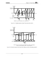
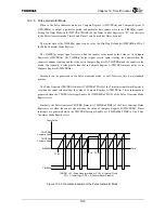
The level of the TIMER[1:0] output signal stays in the High level in this mode. Figure 12.3.1 shows
an outline of the count operation and generation of interrupts when in the Interval Timer mode and
Figure 12.3.2 shows the operation when using an external input clock.
Summary of Contents for TMPR4925
Page 1: ...64 Bit TX System RISC TX49 Family TMPR4925 Rev 3 0 ...
Page 4: ......
Page 15: ...Handling Precautions ...
Page 16: ......
Page 18: ...1 Using Toshiba Semiconductors Safely 1 2 ...
Page 40: ...3 General Safety Precautions and Usage Considerations 3 18 ...
Page 42: ...4 Precautions and Usage Considerations 4 2 ...
Page 43: ...TMPR4925 ...
Page 44: ......
Page 54: ...Chapter 1 Features 1 8 ...
Page 58: ...Chapter 2 Block Diagram 2 4 ...
Page 88: ...Chapter 4 Address Mapping 4 12 ...
Page 226: ...Chapter 8 DMA Controller 8 58 ...
Page 260: ...Chapter 9 SDRAM Controller 9 34 ...
Page 480: ...Chapter 15 Interrupt Controller 15 32 ...
Page 554: ...Chapter 19 Real Time Clock RTC 19 8 ...
Page 555: ...Chapter 20 Removed 20 1 20 Removed ...
Page 556: ...Chapter 20 Removed 20 2 ...
Page 564: ...Chapter 21 Extended EJTAG Interface 21 8 ...
Page 580: ...Chapter 22 Electrical Characteristics 22 16 ...
Page 588: ...Chapter 24 Usage Notes 24 2 ...

