Chapter 12 Timer/Counter
12-7
12.3.6 Watchdog
Timer
Mode
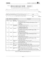
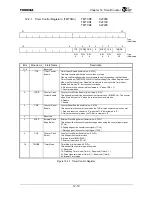
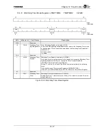
The Watchdog Timer mode is used to monitor system anomalies. The software periodically clears the
counter and judges an anomaly to exist if the counter is not cleared within a specified period of time.
Then, either the TX4925 is internally reset or an NMI is signaled to the TX49/H2 core. Set the Timer
mode field (TMTCR2.TMODE) of the Timer Control Register to “10” to set the timer to the Watchdog
Timer mode. This mode can only be used by Timer 2.
Use the Watchdog Reset bit (WR) of the Chip Configuration Register (CCFG) to select whether to
perform an internal reset or signal an NMI. Set this bit to “1” to select Watchdog Reset, or set it to “0”
to select NMI Signaling.
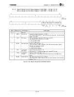
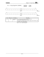
When the timer count reaches the value programmed in Compare Register A (TMCPRA2), the
Watchdog Timer TMCPRA Match Status bit in the Timer Interrupt Status Register (TMTISR2.TWIS) is
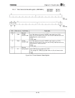
set. Either the watchdog timer reset or NMI is issued if the Timer Watchdog Enable bit in the Watchdog
Timer Mode Register (TMWTMR2.TWIE) is set.
When the watchdog timer reset is selected, the Watchdog Reset Status bit in the Chip Configuration
Register (CCFG.WDRST) is set. The entire TX4925 is initialized but the configuration registers.
There are three ways of stopping NMI signaling from being performed.
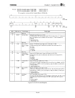
(1) Clear the Watchdog Timer Interrupt Status bit (TMTISR2.TWIS) of the timer Interrupt Status
Register.
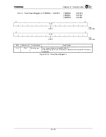
(2) Clear the counter by writing “1” to the Watchdog Timer Clear bit (TMWTMR2.TWC) of the
Watchdog Timer Mode Register.
(3) Clear the Watchdog Timer Interrupt Enable bit (TMWTMR2.TWIE) while the Watchdog Timer
Disable bit (TMWTMR2.WDIS) is still set.
It is possible to stop the counter when in the Watchdog Timer mode by clearing the Timer Counter
Enable bit (TMTCR2.TCE) of the Timer Control Register while the Watchdog Timer Disable bit
(TMWTMR2.WDIS) of the Watchdog Timer Mode Register is set to “1”.
It is also possible to stop the counter by clearing the Counter Clock Divide Cycle Enable bit
(TMTCR2.CCDE) of the Timer Control Register when the internal clock is being used as the counter
clock.
It is not possible to directly write “0” to the Watchdog Timer Disable bit (TMWTMR2.WDIS). There
are two ways to clear this bit.
(1) Clear the Watchdog Timer Interrupt Enable bit (TMWTMR2.WDIS)
(2) Clear the Timer Counter Enable bit (TMTCR2.TCE) of the Timer Control Register
Summary of Contents for TMPR4925
Page 1: ...64 Bit TX System RISC TX49 Family TMPR4925 Rev 3 0 ...
Page 4: ......
Page 15: ...Handling Precautions ...
Page 16: ......
Page 18: ...1 Using Toshiba Semiconductors Safely 1 2 ...
Page 40: ...3 General Safety Precautions and Usage Considerations 3 18 ...
Page 42: ...4 Precautions and Usage Considerations 4 2 ...
Page 43: ...TMPR4925 ...
Page 44: ......
Page 54: ...Chapter 1 Features 1 8 ...
Page 58: ...Chapter 2 Block Diagram 2 4 ...
Page 88: ...Chapter 4 Address Mapping 4 12 ...
Page 226: ...Chapter 8 DMA Controller 8 58 ...
Page 260: ...Chapter 9 SDRAM Controller 9 34 ...
Page 480: ...Chapter 15 Interrupt Controller 15 32 ...
Page 554: ...Chapter 19 Real Time Clock RTC 19 8 ...
Page 555: ...Chapter 20 Removed 20 1 20 Removed ...
Page 556: ...Chapter 20 Removed 20 2 ...
Page 564: ...Chapter 21 Extended EJTAG Interface 21 8 ...
Page 580: ...Chapter 22 Electrical Characteristics 22 16 ...
Page 588: ...Chapter 24 Usage Notes 24 2 ...

