Chapter 13 Parallel I/O Port
13-2
13.3 Detailed
Description
13.3.1 Selecting PIO Pins
All of the 32-bit PIO signals are shared with other functions. The boot configuration signal (TDO)
and pin configuration register (PCFG) determine which functions will be used. See Sections “3.2 Boot
Configuration”, “3.3 Pin Multiplexing” and “5.2.3 Pin Configuration Register” for more information.
13.3.2 General-purpose Parallel Port
The four following registers are used to control the PIO port.
•
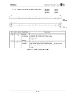
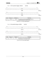
PIO Output Data Register (PIODO)
•
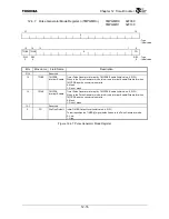
PIO Input Data Register (PIODI)
•
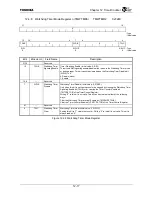
PIO Direction Control Register (PIODIR)
•
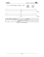
PIO Open Drain Control Register (PIOOD)
PIO signals can be selected by the PIO Direction Control Register (PIODIR) for each bit as either
input or output.
Signals selected as output signals output the values written into the PIO Data Output Register
(PIODO). The PIO Open Drain Control Register (PIOOD) can select whether each bit is either an open
drain output or a totem pole output.
PIO signal status is indicated by the PIO Data Input Register. This register can be read out at any time
regardless of the pin direction settings.
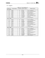
13.4 Registers
Table 13.4.1 PIO Register Map
Reference Offset
Address Bit
Width
Mnemonic
Register
Name
13.4.1
0xF500
32
PIODO
PIO Output Data Register
13.4.2
0xF504
32
PIODI
PIO Input Data Register
13.4.3
0xF508
32
PIODIR
PIO Direction Control Register
13.4.4
0xF50C
32
PIOOD
PIO Open Drain Control Register
Summary of Contents for TMPR4925
Page 1: ...64 Bit TX System RISC TX49 Family TMPR4925 Rev 3 0 ...
Page 4: ......
Page 15: ...Handling Precautions ...
Page 16: ......
Page 18: ...1 Using Toshiba Semiconductors Safely 1 2 ...
Page 40: ...3 General Safety Precautions and Usage Considerations 3 18 ...
Page 42: ...4 Precautions and Usage Considerations 4 2 ...
Page 43: ...TMPR4925 ...
Page 44: ......
Page 54: ...Chapter 1 Features 1 8 ...
Page 58: ...Chapter 2 Block Diagram 2 4 ...
Page 88: ...Chapter 4 Address Mapping 4 12 ...
Page 226: ...Chapter 8 DMA Controller 8 58 ...
Page 260: ...Chapter 9 SDRAM Controller 9 34 ...
Page 480: ...Chapter 15 Interrupt Controller 15 32 ...
Page 554: ...Chapter 19 Real Time Clock RTC 19 8 ...
Page 555: ...Chapter 20 Removed 20 1 20 Removed ...
Page 556: ...Chapter 20 Removed 20 2 ...
Page 564: ...Chapter 21 Extended EJTAG Interface 21 8 ...
Page 580: ...Chapter 22 Electrical Characteristics 22 16 ...
Page 588: ...Chapter 24 Usage Notes 24 2 ...

