Chapter 14 AC-link Controller
14-4
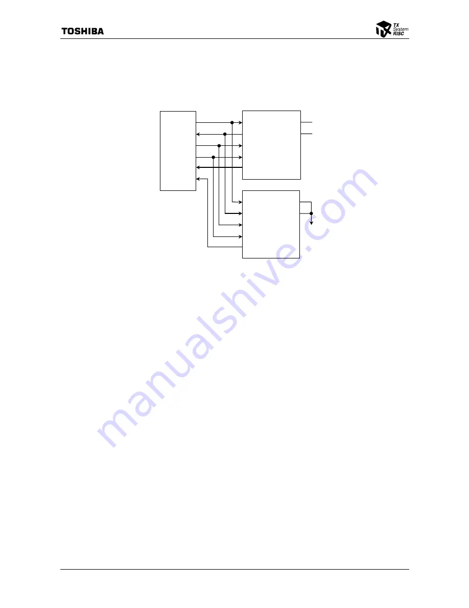
14.3.1.2 5.1 Channel Audio Connection
This sample assumes one CODEC with four DACs mapped to stereo front (3&4) and stereo rear
(7&8) slots, and another CODEC with two DACs mapped to center (6) and LFE (9) slots.
Figure 14.3.2 5.1 Channel Audio Connection Diagram
14.3.2 Pin
Configuration
To utilize ACLC, the Select ACLC (SELACLC) bit in Pin Configuration Register (PCFG) must be
set to 1. Refer to the Sections 3.3 and 5.2.3 for the detail of the pin configuration.
SDIN1
ACRESET
*
BITCLK
SYNC
SDOUT
SDIN0
ACLC
CID0
RESET#
BIT_CLK
SYNC
SDATA_OUT
SDATA_IN
4 Channel Audio CODEC (CODEC ID=’0’)
CID1
CID0
RESET#
BIT_CLK
SYNC
SDATA_OUT
SDATA_IN
2 Channel Audio CODEC (CODEC ID=‘3’)
CID1
GND
Summary of Contents for TMPR4925
Page 1: ...64 Bit TX System RISC TX49 Family TMPR4925 Rev 3 0 ...
Page 4: ......
Page 15: ...Handling Precautions ...
Page 16: ......
Page 18: ...1 Using Toshiba Semiconductors Safely 1 2 ...
Page 40: ...3 General Safety Precautions and Usage Considerations 3 18 ...
Page 42: ...4 Precautions and Usage Considerations 4 2 ...
Page 43: ...TMPR4925 ...
Page 44: ......
Page 54: ...Chapter 1 Features 1 8 ...
Page 58: ...Chapter 2 Block Diagram 2 4 ...
Page 88: ...Chapter 4 Address Mapping 4 12 ...
Page 226: ...Chapter 8 DMA Controller 8 58 ...
Page 260: ...Chapter 9 SDRAM Controller 9 34 ...
Page 480: ...Chapter 15 Interrupt Controller 15 32 ...
Page 554: ...Chapter 19 Real Time Clock RTC 19 8 ...
Page 555: ...Chapter 20 Removed 20 1 20 Removed ...
Page 556: ...Chapter 20 Removed 20 2 ...
Page 564: ...Chapter 21 Extended EJTAG Interface 21 8 ...
Page 580: ...Chapter 22 Electrical Characteristics 22 16 ...
Page 588: ...Chapter 24 Usage Notes 24 2 ...


