Chapter 14 AC-link Controller
14-8
14.3.5 CODEC
Register
Access
By accessing registers in the CODEC, the system software is able to detect or control the CODEC
state. This section describes how to read and write CODEC registers via ACLC. For details about
AC’97 register set and proper sequence to operate CODEC, refer to the AC’97 specification and target
CODEC datasheet.
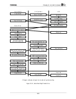
It takes several frame periods for a read or write access to complete. Taking this into account, ACLC
is equipped with a function for reporting CODEC register access completion as status-change or
interrupt.
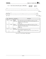
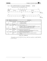
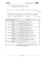
In order to read an AC’97 register, write the access destination CODEC ID and register address in
ACLC CODEC Register Access Register (ACREGACC) with its CODECRD bit set to “1”. After the
ACLC Interrupt Status Register (ACINTSTS)’s REGACC Ready (REGACCRDY) bit is set, the
software is able to get the data returned from the AC’97 by reading the ACREGACC register and issue
another access.
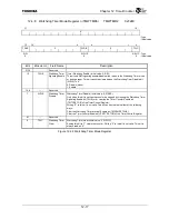
In order to write to an AC’97 register, write the access destination CODEC ID, register address, and
the data in ACLC’s ACREGACC register with ACREGACC.CODECRD bit set to “0”. After the
ACINTSTS.REGACCRDY bit has been set, the software is able to issue another access.
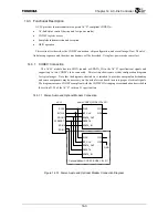
In case of 5.1 channel audio connection example (Figure 14.3.2), because the secondary CODEC has
CODEC ID of ‘3’, the software must write ‘3’ into ACREGACC.CODECID field when it issues
secondary CODEC register access.
Summary of Contents for TMPR4925
Page 1: ...64 Bit TX System RISC TX49 Family TMPR4925 Rev 3 0 ...
Page 4: ......
Page 15: ...Handling Precautions ...
Page 16: ......
Page 18: ...1 Using Toshiba Semiconductors Safely 1 2 ...
Page 40: ...3 General Safety Precautions and Usage Considerations 3 18 ...
Page 42: ...4 Precautions and Usage Considerations 4 2 ...
Page 43: ...TMPR4925 ...
Page 44: ......
Page 54: ...Chapter 1 Features 1 8 ...
Page 58: ...Chapter 2 Block Diagram 2 4 ...
Page 88: ...Chapter 4 Address Mapping 4 12 ...
Page 226: ...Chapter 8 DMA Controller 8 58 ...
Page 260: ...Chapter 9 SDRAM Controller 9 34 ...
Page 480: ...Chapter 15 Interrupt Controller 15 32 ...
Page 554: ...Chapter 19 Real Time Clock RTC 19 8 ...
Page 555: ...Chapter 20 Removed 20 1 20 Removed ...
Page 556: ...Chapter 20 Removed 20 2 ...
Page 564: ...Chapter 21 Extended EJTAG Interface 21 8 ...
Page 580: ...Chapter 22 Electrical Characteristics 22 16 ...
Page 588: ...Chapter 24 Usage Notes 24 2 ...

