Chapter 14 AC-link Controller
14-13
14.3.6.5 Sample-data FIFO
For a transmission stream, as long as ACLC Control Enable Register (ACCTLEN) allows that
transmission and the FIFO has any room to fill data in, the FIFO issues a request via the REQ
latch. On the other side, when a transmission FIFO receives a data-request from the link-side, it
provides data with valid-flag set if it has any valid data. If it has no valid data, it responds with
valid-flag unset and an underrun error bit is set.
At the transmit-data DMA start-up, until the FIFO becomes full, it responds to the link-side
with valid-flag unset, in order to maximize the buffering effect. Therefore, the DMA size must be
the FIFO depth or more.
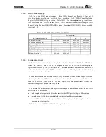
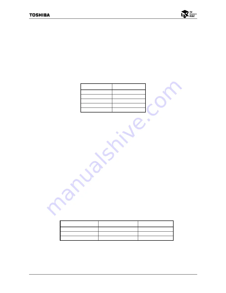
Table 14.3.8 Transmission FIFO Depth
Data-stream
FIFO Depth (Word)
PCM L&R out
3
Surround L&R out
3
Center out
2
LFE out
2
Modem Line 1 out
1
The link-side drives the slot-valid bit and slot-data on AC-link. When underrun occurs, these
bits are driven to all ‘0’.
For a reception stream, as long as the FIFO has any valid data, the FIFO issues a request via the
REQ latch. On the other side, when ACCTLEN allows that reception and the link-side issues a
data strobe, the FIFO stores the valid data. If the FIFO is full when it receives a data strobe, the
data is discarded and an overrun error bit is set.
14.3.6.6 Error Detection and Recovery
In most usages, since the CODEC continuously requests sample-data transmission and
reception, after DMA is finished, underrun and overrun will occur. The procedure described
below allows the software to determine whether an error has occurred during DMA operation.
The software sets ACLC Control Enable Register (ACCTLEN)’s Error Halt Enable
(xxxxEHLT) bit before it starts a DMA channel. After it starts the DMA channel, it waits until
ACLC Interrupt Status Register (ACINTSTS)’s Underrun or Overrun Error (xxxxERR) bit is set.
When the event is detected, the software checks DMA Channel Control Register (DMCCRn)’s
Transfer Active (XFACT) bit and ACLC DMA Request Status Register (ACDMASTS)’s Request
(xxxxDMA) bit and determines the DMA completion status as follows.
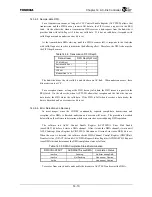
Table 14.3.9 DMA Completion Status Determination
DMCCRn.XFACT ACDMASTS.xxxxDMA
Completion
Status
Inactive
Pending
No Error during DMA
Inactive
Not Pending
Underrun or Overrun
Active
*
Underrun or Overrun
To recover from error, disable and enable the stream via ACCTLEN, and restart the DMA.
Summary of Contents for TMPR4925
Page 1: ...64 Bit TX System RISC TX49 Family TMPR4925 Rev 3 0 ...
Page 4: ......
Page 15: ...Handling Precautions ...
Page 16: ......
Page 18: ...1 Using Toshiba Semiconductors Safely 1 2 ...
Page 40: ...3 General Safety Precautions and Usage Considerations 3 18 ...
Page 42: ...4 Precautions and Usage Considerations 4 2 ...
Page 43: ...TMPR4925 ...
Page 44: ......
Page 54: ...Chapter 1 Features 1 8 ...
Page 58: ...Chapter 2 Block Diagram 2 4 ...
Page 88: ...Chapter 4 Address Mapping 4 12 ...
Page 226: ...Chapter 8 DMA Controller 8 58 ...
Page 260: ...Chapter 9 SDRAM Controller 9 34 ...
Page 480: ...Chapter 15 Interrupt Controller 15 32 ...
Page 554: ...Chapter 19 Real Time Clock RTC 19 8 ...
Page 555: ...Chapter 20 Removed 20 1 20 Removed ...
Page 556: ...Chapter 20 Removed 20 2 ...
Page 564: ...Chapter 21 Extended EJTAG Interface 21 8 ...
Page 580: ...Chapter 22 Electrical Characteristics 22 16 ...
Page 588: ...Chapter 24 Usage Notes 24 2 ...

