Chapter 14 AC-link Controller
14-15
14.3.8 Interrupt
ACLC generate two kinds of interrupt to the interrupt controller as below.
•
ACLC Interrupt
Logical OR of all the valid bits of ACLC Interrupt Masked Status Register (ACINTMSTS) is
connected. Refer to section 14.4.5.
•
ACLCPME Interrupt
This interrupt shows the wake-up from CODEC in AC-link low-power mode.
Refer to the description for ACLC Control Enable Register (ACCTLEN)’s Wake-up Enable
(WAKEUP) bit in section 14.4.1.
14.3.9 AC-link
Low-power
Mode
The AC’97 specification makes provision for saving power during system suspension by powering-
down both the controller and CODEC except the minimum circuit to detect modem RING/Caller-ID
event and wake up the system. AC’97 CODEC is required to go into the low-power mode when they
receive a special register-write access. In this mode, the AC-link controller must drive all output signals
to low level to allow the CODEC digital I/O power cut.
ACLC provides ‘AC-link low-power mode’ setting. When this mode is enabled by ACLC Control
Enable Register (ACCTLEN)’s Enable AC-link Low-power Mode (LOWPWR) bit, all the output
signals except the ACRESET* signal to the AC-link are forced to low level.
The AC-link will be reactivated out of the low-power mode when the SYNC signal is driven high for
1
µ
s or longer by the AC-link controller while the BITCLK signal is inactive. The software is
responsible for controlling the length of this period.
ACLC also provides the ‘wake-up’ function. While this function is enabled by ACCTLEN Register’s
Enable Wake-up (WAKEUP) bit, high-level input at any SDIN[x] signal will force ACLCPME interrupt
assertion.
When ACLCPME interrupt is recognized, the software must disable the low-power mode and assert
warm reset to the AC-link via ACCTLEN Register’s Enable Warm Reset (WRESET) bit. After the
warm reset is deasserted, the CODEC will start providing the BITCLK signal, and then ACLC will
generate the SYNC signal for usual AC-link frames.
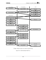
Refer to section B.5.1 of AC’97 specification revision 2.1 for the power-down and wake-up sequence
in AC-link power-down mode.
Summary of Contents for TMPR4925
Page 1: ...64 Bit TX System RISC TX49 Family TMPR4925 Rev 3 0 ...
Page 4: ......
Page 15: ...Handling Precautions ...
Page 16: ......
Page 18: ...1 Using Toshiba Semiconductors Safely 1 2 ...
Page 40: ...3 General Safety Precautions and Usage Considerations 3 18 ...
Page 42: ...4 Precautions and Usage Considerations 4 2 ...
Page 43: ...TMPR4925 ...
Page 44: ......
Page 54: ...Chapter 1 Features 1 8 ...
Page 58: ...Chapter 2 Block Diagram 2 4 ...
Page 88: ...Chapter 4 Address Mapping 4 12 ...
Page 226: ...Chapter 8 DMA Controller 8 58 ...
Page 260: ...Chapter 9 SDRAM Controller 9 34 ...
Page 480: ...Chapter 15 Interrupt Controller 15 32 ...
Page 554: ...Chapter 19 Real Time Clock RTC 19 8 ...
Page 555: ...Chapter 20 Removed 20 1 20 Removed ...
Page 556: ...Chapter 20 Removed 20 2 ...
Page 564: ...Chapter 21 Extended EJTAG Interface 21 8 ...
Page 580: ...Chapter 22 Electrical Characteristics 22 16 ...
Page 588: ...Chapter 24 Usage Notes 24 2 ...

