Chapter 17 Serial Peripheral Interface
17-2
17.2 Block
Diagram
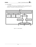
The SPI Module primarily consists of a 16-bit SPI Data Register (SPDR), a 16-bit Shift Register, a 16-bit
Transmitter Buffer, a 16-bit Receiver Buffer, a Baud Rate Generator, an Inter Frame Time Counter, and
Interrupt Logic. A block diagram of the SPI Module is shown in Figure 17.2.1.
Figure 17.2.1 SPI Block Diagram
SPDR
Receive Buffer (FIFO )
Transmit Buffer (FIFO )
Write
Read
Shift Register
SPIIN
SPIOUT
SPICLK
Baud Rate
Generator
Inter Frame
Space Timer
Interrupt
Logic
Bus I/F
IM-Bus
Summary of Contents for TMPR4925
Page 1: ...64 Bit TX System RISC TX49 Family TMPR4925 Rev 3 0 ...
Page 4: ......
Page 15: ...Handling Precautions ...
Page 16: ......
Page 18: ...1 Using Toshiba Semiconductors Safely 1 2 ...
Page 40: ...3 General Safety Precautions and Usage Considerations 3 18 ...
Page 42: ...4 Precautions and Usage Considerations 4 2 ...
Page 43: ...TMPR4925 ...
Page 44: ......
Page 54: ...Chapter 1 Features 1 8 ...
Page 58: ...Chapter 2 Block Diagram 2 4 ...
Page 88: ...Chapter 4 Address Mapping 4 12 ...
Page 226: ...Chapter 8 DMA Controller 8 58 ...
Page 260: ...Chapter 9 SDRAM Controller 9 34 ...
Page 480: ...Chapter 15 Interrupt Controller 15 32 ...
Page 554: ...Chapter 19 Real Time Clock RTC 19 8 ...
Page 555: ...Chapter 20 Removed 20 1 20 Removed ...
Page 556: ...Chapter 20 Removed 20 2 ...
Page 564: ...Chapter 21 Extended EJTAG Interface 21 8 ...
Page 580: ...Chapter 22 Electrical Characteristics 22 16 ...
Page 588: ...Chapter 24 Usage Notes 24 2 ...


