Chapter 5 Configuration Register
5-1
5. Configuration
Register
5.1 Outline
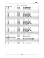
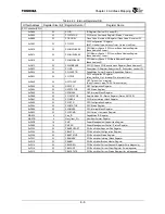
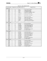
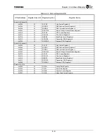
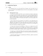
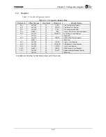
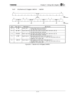
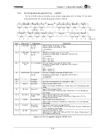
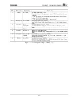
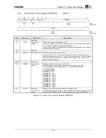
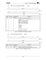
The configuration registers set up and control the basic functionality of the entire TX4927. Refer to
Section 5.2 for details of each configuration register. Also refer to sections mentioned in the description
about each bit field.
5.1.1 Detecting
G-Bus
Timeout
The G-Bus is an internal bus of the TX4925. Access to each address on the G-Bus is completed upon
a bus response from the accessed address. If an attempt is made to access an undefined physical address
or if a hardware failure occurs, no bus response is made. If a bus response does not occur, the bus access
will not be completed, leading to a system halt. To solve this problem, the TX4925 is provided with a
G-Bus timeout detection function. This function forcibly stops bus access if no bus response occurs
within the specified time.
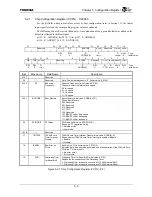
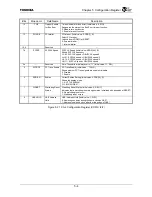
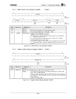
Setting the G-Bus Timeout Error Detection bit (CCFG.TOE) of the chip configuration register
enables the G-Bus timeout detection function. If a bus response does not occur within the G-Bus clock
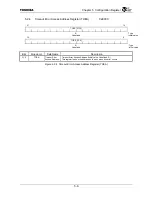
(GBUSCLK) cycle specified in the G-Bus Timeout count register (TOCNT), the G-Bus timeout
detection function makes an error response to force the bus access to end. The accessed address is
stored to the timeout error access address register (TOEA).
If a timeout error is detected while the TX49/H2 core, as the bus master, is gaining write access to the
G-Bus, the Write-Access Bus Error bit (CCFG.BEOW) is set. Enabling interrupt No. 1 in the interrupt
controller makes it possible to post an interrupt to the TX49/H2 core. If a timeout error is detected while
the TX49/H2 core is gaining read access to the bus, a bus error exception occurs in the TX49/H2 core.
If a timeout error is detected while another G-Bus master (the PCI controller or DMA controller) is
accessing the G-Bus, an error bit in that controller is set, which can be used to post an interrupt. Refer to
the descriptions of each controller for details.
If the TRST* signal is deasserted, it is assumed that an EJTAG probe is connected, so the G-Bus
timeout detection feature is disabled.
Summary of Contents for TMPR4925
Page 1: ...64 Bit TX System RISC TX49 Family TMPR4925 Rev 3 0 ...
Page 4: ......
Page 15: ...Handling Precautions ...
Page 16: ......
Page 18: ...1 Using Toshiba Semiconductors Safely 1 2 ...
Page 40: ...3 General Safety Precautions and Usage Considerations 3 18 ...
Page 42: ...4 Precautions and Usage Considerations 4 2 ...
Page 43: ...TMPR4925 ...
Page 44: ......
Page 54: ...Chapter 1 Features 1 8 ...
Page 58: ...Chapter 2 Block Diagram 2 4 ...
Page 88: ...Chapter 4 Address Mapping 4 12 ...
Page 226: ...Chapter 8 DMA Controller 8 58 ...
Page 260: ...Chapter 9 SDRAM Controller 9 34 ...
Page 480: ...Chapter 15 Interrupt Controller 15 32 ...
Page 554: ...Chapter 19 Real Time Clock RTC 19 8 ...
Page 555: ...Chapter 20 Removed 20 1 20 Removed ...
Page 556: ...Chapter 20 Removed 20 2 ...
Page 564: ...Chapter 21 Extended EJTAG Interface 21 8 ...
Page 580: ...Chapter 22 Electrical Characteristics 22 16 ...
Page 588: ...Chapter 24 Usage Notes 24 2 ...

