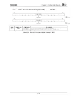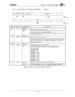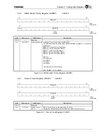
Chapter 5 Configuration Register
5-4
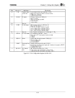
Bits Mnemonic Field
Name
Description
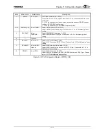
14 TOE
Timeout Enable
for Bus Error
Timeout Enable for Bus Error (Initial value: 0, R/W)
Designates the state of the Bus Error time-out function.
0: Disable time out function.
1: Enable time out function.
13
PCIARB
PCI arbiter
PCI arbiter. (Initial value: ˜ADDR[1], R)
Select PCI arbiter.
Latched from ADDR[1] at RESET.
0: External arbiter
1: Internal arbiter
12:8
⎯
Reserved
⎯
7:6 SYSSP
SYSCLK
Speed
SYSCLK Speed (Initial value: ADDR[4:3], R)
Shows SYSCLK frequency.
LL: 00: SYSCLK speed = GBUSCLK speed/4
LH: 01: SYSCLK speed = GBUSCLK speed/3
HL: 10: SYSCLK speed = GBUSCLK speed/2
HH: 11: SYSCLK speed = GBUSCLK speed
5:4
⎯
Reserved
Note: These bits are always set to “11” (Initial value: 11, R/W).
3
PCTRCE
PC Trace Enable
PC Trace Enable (Initial value: ˜
TDO, R)
Shows whether PC Trace signals are enable or disable.
0: Disable
1: Enable
2 ENDIAN
Endian
Current Endian Setting (Initial value: ADDR[14], R)
Shows the endian mode.
L: 0: LITTLE ENDIAN
H: 1: BIG ENDIAN
1 WDRST
Watchdog Reset
Status
Watchdog Reset Status (Initial value: 0, R/W1C)
Indicates that a watchdog reset was generated. Initialized with assertion of RESET
*
.
0: No watchdog reset occur
1: Watchdog reset occurs
0 UAEHOLD
UAE Address
Hold
UAE
*
Address Hold (Initial value: 1, R/W)
0: Address goes away during the same clock as UAE
*
.
1: Address is held one clock after the rising edge of UAE
*
.
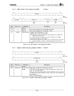
Figure 5.2.1 Chip Configuration Register (CCFG)
(2/2)
Summary of Contents for TMPR4925
Page 1: ...64 Bit TX System RISC TX49 Family TMPR4925 Rev 3 0 ...
Page 4: ......
Page 15: ...Handling Precautions ...
Page 16: ......
Page 18: ...1 Using Toshiba Semiconductors Safely 1 2 ...
Page 40: ...3 General Safety Precautions and Usage Considerations 3 18 ...
Page 42: ...4 Precautions and Usage Considerations 4 2 ...
Page 43: ...TMPR4925 ...
Page 44: ......
Page 54: ...Chapter 1 Features 1 8 ...
Page 58: ...Chapter 2 Block Diagram 2 4 ...
Page 88: ...Chapter 4 Address Mapping 4 12 ...
Page 226: ...Chapter 8 DMA Controller 8 58 ...
Page 260: ...Chapter 9 SDRAM Controller 9 34 ...
Page 480: ...Chapter 15 Interrupt Controller 15 32 ...
Page 554: ...Chapter 19 Real Time Clock RTC 19 8 ...
Page 555: ...Chapter 20 Removed 20 1 20 Removed ...
Page 556: ...Chapter 20 Removed 20 2 ...
Page 564: ...Chapter 21 Extended EJTAG Interface 21 8 ...
Page 580: ...Chapter 22 Electrical Characteristics 22 16 ...
Page 588: ...Chapter 24 Usage Notes 24 2 ...

