TOSHIBA
5 - 9
5.10
Braking Characteristics
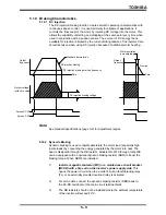
5.10.1 DC Injection
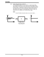
The DC injection braking function creates smooth operating characteristics with
continuous phase control. It is used primarily for alignment applications. It
controls the final coast of the motor by injecting DC voltage into the motor. This
allows the capability of starting and stopping at the same point every time when
used in conjunction with a position sensor. The amount of DC energy that is
available for injection is limited by the current limiting feature of the inverter. Care
should be taken when using DC injection because of additional motor heating.
Standard deceleration
DC injection braking start-up frequency
DC injection braking voltage
Output
frequency
Free-run
Time
Time
DC injection braking
Across ST-CC
Across F-CC
Output voltage
(effective value)
Motor excitation
de-energizing
Output
frequency
Note:
See standard specifications (page 3-2) for adjustment ranges.
5.10.2 Dynamic Braking
Dynamic braking is used to rapidly decelerate the motor load (especially high
inertia loads) by converting the energy generated by the motor into heat. The
heat is dissipated through the DB resistor. Models G2+2010 through G2+430K
can be equipped with an optional dynamic braking resistor (DBR) to boost the
braking torque. When DBR's are installed:
1)
Install a magnetic contactor (MC) or a molded case circuit breaker
(MCCB) with a trip coil on the inverter's power supply side.
This
opens the power circuit when the inverter's built-in fault detecting relay
(FL) or an externally mounted overload relay is activated.
2)
For all models, connect the dynamic braking resistor (DBR) bank to
the PA-PB terminals of the main circuit terminal block.
3)
The DB resistors should not be installed where the ambient temperature
of the inverter will exceed 40°C.
Summary of Contents for TOSVERT-130G2+
Page 112: ...TOSHIBA 10 6 Schematics 10 17 ...


