TOSHIBA
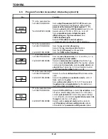
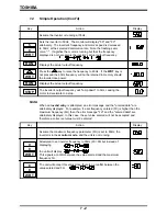
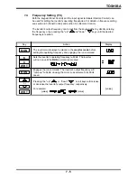
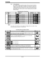
The parameter can also be changed by using the scroll keys
"up" or "down" . When 7.5 has been reached the
WRT
key should be pressed to set the new value.
7 - 3
7.3
Function Access/Set Methods
7.3.1
First Functions
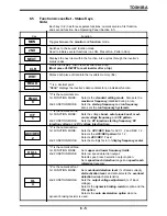
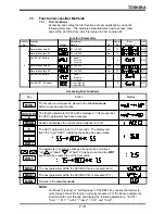
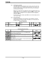
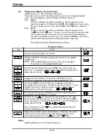
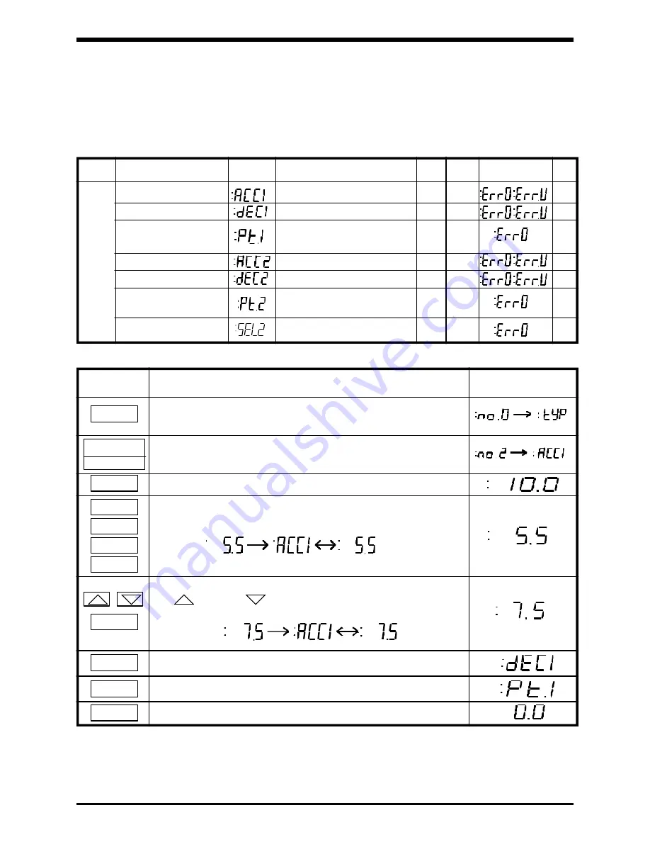
Accessing and setting the first functions are accomplished by using the
following procedure. The example below illustrates how to access, read,
and set the ACC/DEC file, which is located in First Function #2.
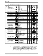
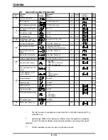
Function Parameters
Acceleration time #1
0.1 to 6000
sec
10
8-21
Deceleration time #1
0.1 to 6000
sec
10
8-21
Acc/Dec #1 pattern
0: Linear
1: S-curve
0
8-21
2: C-curve
2
Acceleration time #2
0.1 to 6000
sec
10
8-21
Deceleration time #2
0.1 to 6000
sec
10
8-21
Acc/Dec #2 pattern
0: Linear
1: S-curve
1
8-21
2: C-curve
Acc/Dec #1, #2 select
0: Acc/Dec #1
0
8-21
1: Acc/Dec #2
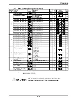
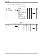
Function Function
Adjustment
Factory
Error
Ref.
No.
Name
Display
Range
Unit
Set
Message
Page
Accessing First Functions
Key
Action
Display
The inverter must always be placed in the
function mode
before accessing any function.
The function parameter ACC1 will be displayed. This means that
the ACC1 parameter has been accessed.
Reads and displays the current value assigned to ACC1.
The ACC1 parameter is set to 5.5 seconds. The display will
flash "5.5" and "ACC1" indicating the setting has been made.
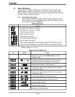
MON
READ
5
.
5
WRT
The next parameter within the ACC/DEC file is accessed (dec1)
The next parameter within the ACC/DEC file is accessed (Pt.1)
Returns to the
monitor mode.
WRT
NEXT
NEXT
MON
ACC/DEC
2
Note:
Continued "pressing" or "holding down" of the NEXT key causes the inverter to
cycle through the entire function currently accessed. For the above example the
inverter would cycle through and display the following parameters: ":ACC1",
":dec1", ":Pt.1", ":ACC2", ":dec2", ":Pt.2", and ":Sel2".
Summary of Contents for TOSVERT-130G2+
Page 112: ...TOSHIBA 10 6 Schematics 10 17 ...

