TOSHIBA
8.7
Operating Functions - Descriptions and Examples (Cont'd)
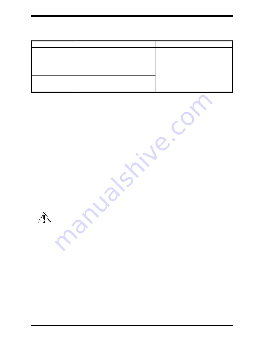
Cause of fault
Reset Process
Reset Failure Conditions
Overcurrent
Tries to restart 5 times in succession
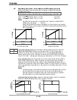
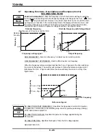
The reset process follows this chart
Overload
1st reset: 1 sec. after problem occurs.
unless a fault, other than those listed,
2nd reset: 2 sec. after initial restart.
occurs. If this happens the inverter will
3rd reset: 4 sec. after 2nd restart try.
not try to reset.
4th reset: 8 sec. after 3rd restart try.
5th reset: 16 sec. after 4th restart try.
Overvoltage
Trips, displays OP, sets fault relay until
overvoltage condition is removed.
Fault relay will be cleared after reset.
8 - 25
Auto Reset Conditions
Note:
The cause of the fault(s) could be from an instantaneous power interrupt.
While preparing for a reset, the auto-reset function causes the fault code "0.0" to be
displayed alternately on the monitor display. Fault-detection signals are not output during
the inverter's reset process. If the cause of the failure has not been corrected, then the
intervals before each attempted reset will be prolonged. See above chart.
If the load exhibits an extremely large amount of inertia (WK)
2
, automatic restart using
the procedure described above may not work.
CAUTION
Before using the inverter's retry (auto-reset) function, check
to be certain that the auto-reset procedure will not damage
or otherwise cause problems for the load
ma-
chine system when the inverter's retry operations are being
executed.
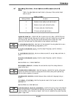
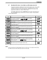
AUTO-RESTART - When selected, the inverter will automatically restart into a free-
rotating motor. This restart will occur
only after an instantaneous power interruption has
occurred. The function allows the inverter to sample the speed of the free-rotating motor
during the interruptions and output a matching frequency when power is reapplied. This
assures smooth restarts of a free-running motor when an instantaneous power loss has
occurred such as when the system is switched from a commercial bypass run to an
inverter run.
Note:
No restart is tried when any of the following messages is displayed on the inverter's
monitor display:
"OCA" Overcurrent (transistor short-circuited at start-up)
"OCL"
Overcurrent (load end short-circuit at start-up)
"OCr"
Overcurrent (overcurrent through the regenerative discharge resistor)
"EF"
Ground fault
"E"
Emergency stop
"EEP" E
2
PROM failure
Note:
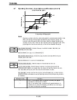
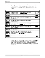
With ArSt=0, the inverter will restart at 0Hz and increase up to the initial running
frequency. With ArSt=1, the inverter will restart at the running frequency of the motor
and will increase up to the initial frequency of the inverter.
REGENERATION POWER RIDE THROUGH CONTROL - Uses regenerative energy
to extend the inverter's power ride through capability during momentary power dropouts.
Summary of Contents for TOSVERT-130G2+
Page 112: ...TOSHIBA 10 6 Schematics 10 17 ...

