TOSHIBA
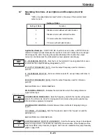
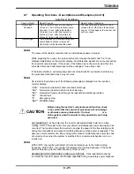
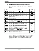
OUTPUT VOLTAGE ADJUSTMENT - Specifies the percent of input voltage which is
seen as the inverter's output voltage.
REGENERATIVE BRAKING SELECTION - Selection of the appropriate parameter
informs the inverter system whether or not a dynamic braking resistor (DBR) is used.
If (yes), then whether or not there is overload detection.
LENGTHENED DECELERATION (Auto-deceleration on the : Pb=0) - Automatically
lengthens the deceleration time to prevent over-voltage trips.
TG/PG * or PID - Informs the inverter of either tach generator (TG)/pulse generator (PG)
feedback, proportional/integral/differential (PID) control, or nothing at all.
PROPORTIONAL GAIN - Sets the gain of the TG/PG or PID controlled input signal.
INTEGRATION GAIN - Adjusts the period of integration when comparing the set point
to the feed back signal.
DIFFERENTIAL GAIN - Stabilizes the system when hunting occurs.
LAG-TIME GAIN - Adjusts the time of response when a change in the feed back signal
is seen.
TG/PG FEEDBACK SELECTION - Selects the type of speed feedback control signal to
be used.
PG FEEDBACK GAIN (Coefficient of TG/PG conversion) - Adjusts the drive to respond
correctly to the external pulse generator.
* TG/PG requires the use of multi-option board.
ACC/DEC
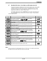
DISPLAY FREQUENCY SCALER - Used to display revolution speed and linear speed.
SEE SECTION 5.8 FOR EXAMPLE.
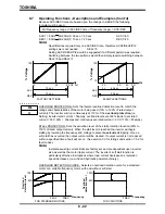
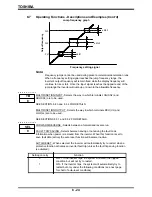
LOW SPEED DETECTION - Outputs a signal when the inverter's output frequency is
greater than or equal to the selected low speed detection frequency.
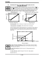
SPEED REACH SELECTION - Selects the option to output a signal when an
ACC/DEC is complete or when the inverter's output frequency is within a selected
range. The range is selected by the following two functions.
SPEED REACH DETECTION RANGE - Specifies a range of frequencies, above and
below the speed reach reference frequency, which when detected will output a signal.
SPEED REACH REFERENCE - Specifies the speed reach detection frequency. When
the inverters output frequency is within the range specified by the Speed reach reference
(± speed reach accuracy), a signal will be output.
SEE SECTION 8.5 FOR EXAMPLES.
8.7
Operating Functions - Descriptions and Examples (Cont'd)
8 - 27
2ND
2
2ND
3
UL/LL
2ND
2ND
4
OL
REF
5
Summary of Contents for TOSVERT-130G2+
Page 112: ...TOSHIBA 10 6 Schematics 10 17 ...

