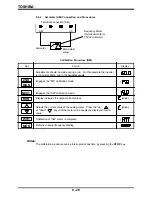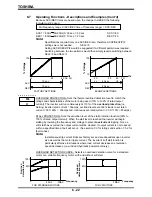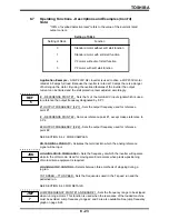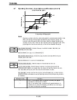
TOSHIBA
8.7
Operating Functions - Descriptions and Examples (Cont'd)
PWM CARRIER FREQUENCY - Selects the inverter's PWM carrier frequency.
OPTION TERMINAL SELECTION * - Used in conjunction with multi-function option
boards binary input.
INVERTER NUMBER * - Allows an inverter identification number to be assigned to the
unit.
BAUD RATE * - Selects baud rate.
SEE SECTION 5.4.
RS232C COMMUNICATION DATA BITS * - Used to select the number of RS232C
communication bits for host computer control.
PARITY AND STOP BITS * - Used to select the parity check and stop bits for host
computer control.
INVERTER TO LINE TRANSFER SIGNAL * - Allows a motor load to be transfered
between the inverter and line power by a signal to the inverter.
PATTERN RUN ACTIVATION MODE - Used to activate a pattern run by determining
where the start command will be taken from.
PATTERN TIME SELECTION - Sets the run time of each individual preset speed to
either seconds or minutes.
PATTERN REPEATABILITY - determines how many times the pattern run will repeat
itself.
PATTERN DRIVE TIME (#1~#7) - Sets the run time of each individual preset speed
frequency (SR1~SR7) to be used in the patterned run.
PATTERN DRIVE CHARACTERISTIC (#1~#7) - Selects the type of run for reach pre-
set speed frequency. The selection can be a forward or reverse run, using either
ACC/DEC #1 or ACC/DEC #2.
COMMAND MODE SELECTION - Determines where the inverter can be started and
stopped; (via the touch-pad, terminal strip, or the host computer).
FREQUENCY REFERENCE SETTING MODE SELECTION - Determines where the
frequency signal is accepted by the inverter; (via the touch-pad, terminal strip, or the
host computer).
PARAMETER SETTING MODE SELECTION - Determines where the parameters can
be programmed; (via the touch-pad, or the host computer).
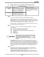
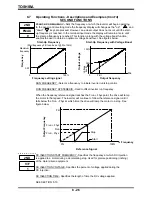
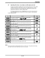
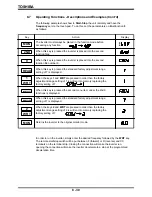
SEE PAGES 8-29 AND 8-30 FOR EXAMPLES
* These parameters require the use of multi-option board
8 - 28
2ND
2ND
6
JOG
7
JMP
2ND
TB
8
2ND
SEL
9
Summary of Contents for TOSVERT-130G2+
Page 112: ...TOSHIBA 10 6 Schematics 10 17 ...

