TOSHIBA
5.0
PWB Layout, Jumpers, and Terminal Connections
5.1
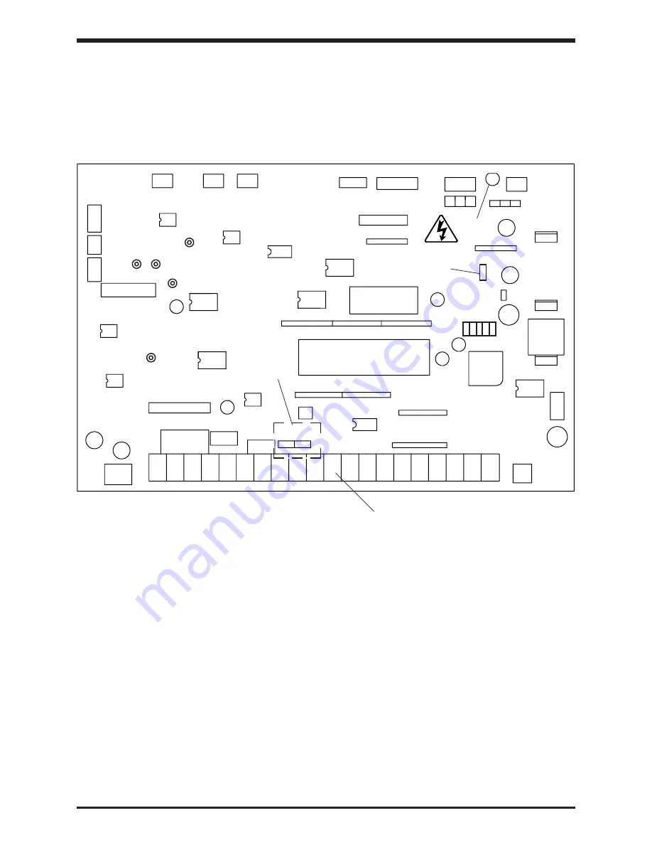
Control Board for P2-4600 through P2-470KB
The following pictorial shows a layout of the major components located on the control
board VF3C-1200.
5 - 1
CN20
CN3
CN2
CN11
See Detail 1
Page 5-3
JP1 JP2
CN10
FL-RY
CN7
See Terminal Block Detail
Page 5-3
CN8
CN1
CN4
CN5
CN6
CN4B
CN4A
CN4C
CP4 CP1
CP2
CP5
CP3
CN12
Note:
1)
CP1, CP2, CP3, CP4, and CP5 are service testpoints.
2)
Do not adjust JP4.
3)
Charge LED indicates charged capacitors.
DO NOT TOUCH internal parts if lighted.
Charge
LED
JP4
Do Not
Adjust
efesotomasyon.com -Toshiba inverter,drive,servo,plc


