TOSHIBA
5.3
Jumper Details
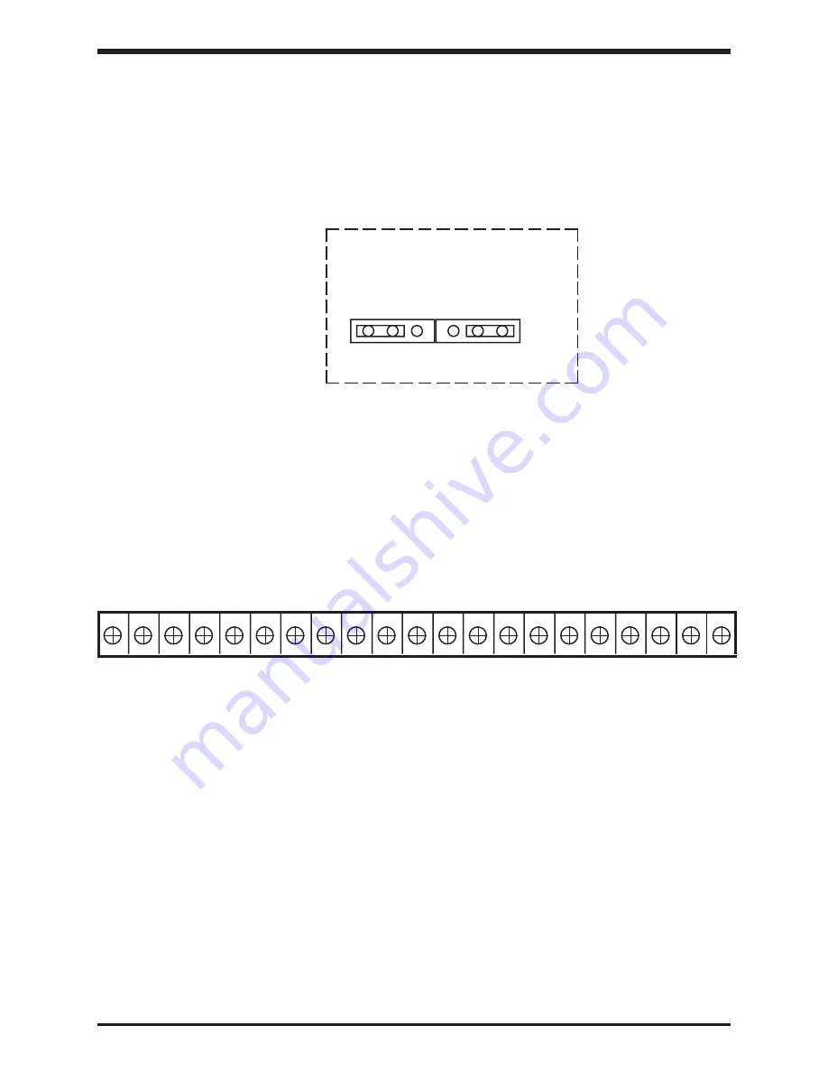
The jumper connections for the printed wiring board on page 5-1 is shown in the
enlarged detail below (See page 5-4 for jumper adjustments).
Only jumpers JP1
and JP2 should be adjusted by the user.
5 - 3
5.4
Control Board Terminal Block Details
The control/driver board terminal block is shown in detail below. Each of the twenty-one
terminals is functionally labeled. See Pages 5-5 and 5-6 for a list of terminal functions.
CC
RST
AD2
JOG
(SS2) (SS3)
FM
FLA
P24
FLC
FLB
PP
AM
LOW
RCH
(UL) (LL)
RR
IV
CC
ST
F
R
CC SSI
Control Board Terminal Block Detail (Reference pages 5-1)
JP2
JP1
I
V
10V
5V
Detail 1 (Reference page 5-1)
efesotomasyon.com -Toshiba inverter,drive,servo,plc


