E6581090
F-4
6
■
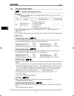
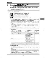
Setting of contact input terminal function
Terminal
symbol
Title
Function
Adjustment
range
Default setting
–
H
Analog input/logic input function selection
0
~
2
0 (voltage input)
–
H
Always active function selection (ST)
1 (standby)
F
H
Input terminal selection 1 (F)
2 (forward run)
R
H
Input terminal selection 2 (R)
3 (reverse run)
S1
H
Input terminal selection 3 (S1)
6 (preset speed 1)
S2
H
Input terminal selection 4 (S2)
7 (preset speed 2)
The parameter below is enabled only when
H
is set to 2.
0~40, 49,
54~57
(See
Section 11.)
–
VI/S3
H
Input terminal selection 5 (VI/S3)
5
~
17
8 (preset speed 3)
Note 1: The
H
parameter (always active function selection) allows you to select a function you
want to keep always active.
Note 2: The
H
parameter (input terminal selection 5 (VI/S3)) is enabled only when
H
is
set to 2.
It is necessary to insert an adequate resistor* between P15 and VI/S3.
(*Recommended resistance : 4.7k
Ω
-1/4W)
■
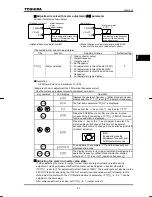
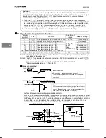
Connection method
1) A-contact input
CC
Input terminal
★
This function is activated when the input and CC
(common) terminals are short-circuited. This function is
used to specify forward/reverse run or preset speed
operation.
Inverter
A-contact switch
In sink logic mode
2) Connection with transistor output (Sink logic)
★
Operation can be controlled by connecting the input and
CC (common) terminals to the output (non-contact switch)
of a programmable controller. This function is used to
specify forward/reverse run or preset speed operation.
Use a transistor that operates at 15Vdc-5mA.
CC
Input terminal
Inverter
Programmable controller
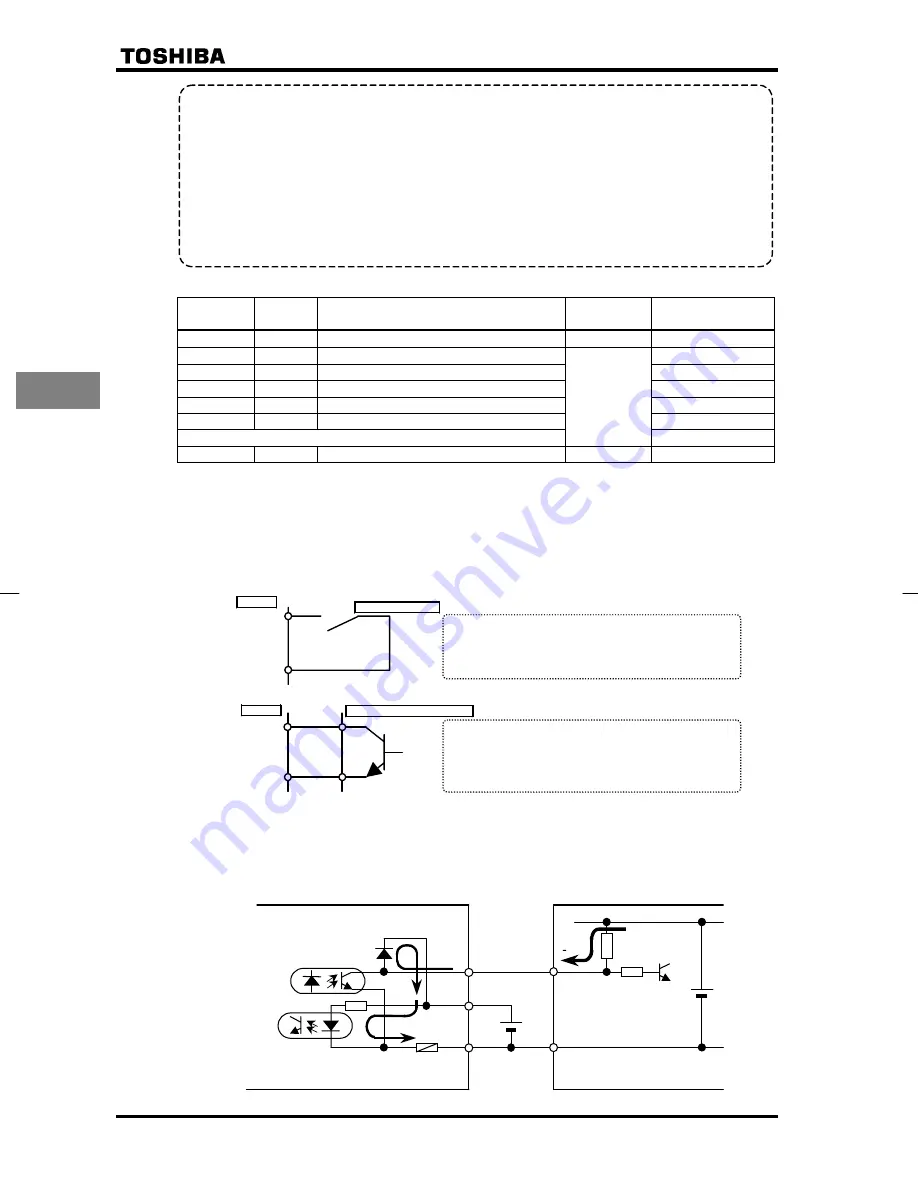
* Interface between inverter and programmable controller
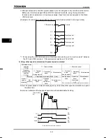
When an open collector output type programmable controller is being used for operation control,
turning off the programmable controller with the inverter left ON causes a wrong signal to flow
into the inverter, as shown in the figure below, because of a difference in control power potential.
To avoid this, be sure to interlock the inverter and the programmable controller so that the
programmable controller cannot be turned off when the inverter is on.
External
+24V power supply
P24
COM
Fuse
Fuse blowout
detection circuit
Internal
+15V power supply
+15V
Programmable controller
Inverter
•
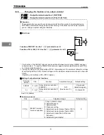
Function
These parameters are used to specify a function for each individual input terminal. With these
parameters allowing selection from among 45 functions for each input terminal, you can design
a system with great flexibility. (For
H
(input terminal selection 5), you can make a
selection from among 13 functions.)
*1 Using the
H
parameter, you can select a function between analog input (frequency
command input) and contact input for the VI/S3 terminal. The VI/S3 terminal is set by default
as a voltage signal input terminal. When using the VI/S3 terminal as a contact input terminal,
you need to set
H
to 2 (contact input enabled), and then to specify a contact input
function for it, using
H
, because it is set by default as a voltage signal input terminal.
Note: Do not set
H
parameter if VI/S3 terminal is not used as contact input.


