E6581090
F-29
6
■
Communications parameters (Common serial options)
The data transfer rate, parity type, inverter ID number and communication error trip time can be
changed from the operation panel or the computer on the network.
Title
Function
Adjustment range
Default setting
H
Communication baud rate
0: 1200bps
1: 2400bps
2: 4800bps
3: 9600bps
4:19200bps
3
H
Parity (Common serial)
0: Non (non parity)
1: Even (even parity)
2: Odd (odd parity)
1
H
Inverter number
0
~
99
0
H
Communication error trip
time
0: Disabled
1
~
100 (sec)
0
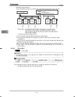
*: Disabled
・・・
Means that the inverter will not trip even if a communication error occurs.
Trip
・・・・・・・
Means that the inverter will trip if a time-out occurs.
If a time-out occurs, the error message “
GTT
” will blink on the display panel.
6.16.1 Using RS232C/RS485 conversion units
■
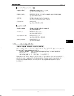
Setting up the communications function
Commands (RUN/STOP commands) entered across a network have priority (over commands
from the operation panel or terminal boards).
■
Data transmission specifications
Item
Specifications
Data transmission
scheme
Half-duplex
Connection scheme
Centralized control
Synchronization
scheme
Asynchronous
Data transfer rate
Default: 9600 baud (parameter setting)
Selectable from among 1200, 2400, 4800, 9600 and 19200 baud
Character
transmission
ASCII mode ... JIS X 0201, 8-bit (fixed, ASCII)
Binary code ... Binary code, 8-bit (fixed)
Stop bit length
Receive (inverter): 1bit, Send (inverter): 2 bits
Error detection
Parity: Selectable among Even, Odd and Non by parameter setting,
Check sum method
Character
transmission format
Receiving: 11-bit, Sending: 12-bit
Order of bit
transmission
Lower-order bits first
Frame length
Variable to a maximum of 17 bytes
■
Examples of connection for RS485 communications
<Example of connection>
Optional unit
Host computer
nC1
nC1
nC1
nC1
nC1
・・・・
・・・・
Optional unit

