background image


E6581595 


A-9 

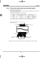
VFNC3-2015 

 2037P 


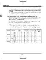
R/L1 S/L2 T/L3

P0

PA/+ PC/- U/T1 V/T2 W/T3

Grounding terminal

M4 screw 

Short-circuit cover

Grounding terminal
(M5 screw)

EMC plate
for installation (Note 1)

M4 screw 

Grounding terminal
M4 screw: 2015, 2202 
M5 screw: 2037

Grounding terminal
M4 screw: 2015, 2202 
M5 screw: 2037


*  Bend the clips on the wiring port of the terminal cover to connect the PO, PA/+, and PC/- terminals. 
 

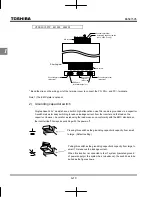
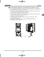
VFNC3S-1001

1004P

2001

2007PL 


R/L1 S/L2/N

P0

PA/+ PC/- U/T1 V/T2 W/T3

M3.5 screw

Grounding capacitor switch
(2001 to 2007 PL only)

Grounding terminal
(M4 screw)

M3.5 screw 

Grounding terminal

Short-circuit cover

EMC plate 
for installation (Note 1)

Grounding 

terminal
(M5 screw)

Grounding terminal


*  Bend the clips on the wiring port of the terminal cover to connect the PO, PA/+, and PC/- terminals. 

Shorting-bar 

Shorting-bar

(M4 screw) 

Summary of Contents for TOSVERT VF-nC3

Page 1: ...eters and data Before Contacting your Toshiba distributor Specifications Inspection and maintenance Warranty 17 17 Appendix Disposal of the inverter NOTICE 1 Make sure that this instruction manual is delivered to the end user of the inverter unit 2 Read this manual before installing or operating the inverter unit and store it in a safe place for reference Instruction Manual Detailed manual 1 phase...

Page 2: ... to injury 1 to people or that these errors will cause damage to physical property 2 1 Such things as injury burns or shock that will not require hospitalization or long periods of outpatient treatment 2 Physical property damage refers to wide ranging damage to assets and materials Meanings of symbols Marking Meaning of marking Indicates prohibition Don t do it What is prohibited will be described...

Page 3: ...e phase output and cannot drive a single phase motor Handling Warning Reference section Disassembly prohibited Never disassemble modify or repair This can result in electric shock fire and injury Call your Toshiba distributor for repairs 2 Prohibited Never remove the terminal block cover when power is on The unit contains many high voltage parts and contact with them will result in electric shock ...

Page 4: ...er the environmental conditions prescribed in the instruction manual Operations under any other conditions can result in malfunction Mount the inverter on a metal plate The rear panel gets very hot Do not install in an inflammable object this can result in fire Do not operate with the terminal block cover removed This can result in electric shock Failure to do so can lead to risk of electric shock...

Page 5: ...pected result as VIA terminal is ON status When supplying power from a wall socket do not exceed the rated capacity of the socket Otherwise this may generate excessive heat which can start a fire 2 2 2 2 2 2 2 2 6 3 1 10 Mandatory action Electrical construction work must be done by a qualified expert Connection of input power by someone who does not have that expert knowledge can result in fire or...

Page 6: ...tor against accidents when the motor unexpectedly restarts 1 3 1 3 3 6 12 3 Mandatory action Turn the input power on only after attaching the terminal block cover When enclosed inside a cabinet and used with the terminal block cover removed always close the cabinet doors first and then turn the power on If the power is turned on with the terminal block cover or cabinet doors open can result in ele...

Page 7: ...t the inverter can not be stopped immediately in breaking communication and this could result in injury and accidents An emergency stop device and the interlock that fit with system specifications must be installed If these are not properly installed the inverter can not be stopped immediately and this could result in injury and accidents 6 19 When sequence for restart after a momentary failure is...

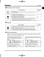
Page 8: ...ry Persons who specialize in the processing of waste and known as industrial waste product collectors and transporters or industrial waste disposal persons Please observe any applicable law regulation rule or ordinance for industrial waste disposal 16 Attach caution labels Shown here are examples of caution labels to prevent in advance accidents in relation to inverters motors and other equipment ...

Page 9: ...oduction Thank you for your purchase of the Toshiba TOSVERT VF nC3 industrial inverter This instruction manual is for the Ver 110 or later CPU of the inverter Please be informed that CPU version will be frequently upgraded ...

Page 10: ...ed operation speeds in 15 steps C 21 4 Setting parameters D 1 4 1 Setting and Display Modes D 1 4 2 How to set parameters D 3 4 3 Functions useful in searching for a parameter or changing a parameter setting D 7 4 4 Checking the region settings selection D 12 4 5 EASY key function D 13 5 Main parameters E 1 5 1 Searching for changes using the history function E 1 5 2 Setting a parameter using the ...

Page 11: ...e F 21 6 10 Preset speed frequencies F 21 6 11 PWM carrier frequency F 22 6 12 Trip less intensification F 24 6 13 PID control F 32 6 14 Setting motor constants F 37 6 15 2nd acceleration deceleration F 40 6 16 Protection functions F 43 6 17 Adjustment parameters F 53 6 18 Operation panel parameter F 55 6 19 Communication function RS485 F 62 6 20 Free notes F 68 7 Operations with external signal G...

Page 12: ...angeable parameters in running K 21 12 Specifications L 1 12 1 Models and their standard specifications L 1 12 2 Outside dimensions and mass L 4 13 Before Contacting your Toshiba distributor Trip information and remedies M 1 13 1 Trip causes warnings and remedies M 1 13 2 Restoring the inverter from a trip M 6 13 3 If the motor does not run while no trip message is displayed M 7 13 4 How to determ...

Page 13: ...If the inverter being used does not conform to those specifications not only will the three phase induction motor not rotate correctly it may also cause serious accidents through overheating and fire Danger label Brand name Model Power supply Motor capacity Inverter main unit Carton box Type indication label Rating label Name plate Danger label 3PH 200V 0 75kW VF nC3 Name plate Setup sheet Inverte...

Page 14: ... the cover while power is applied or for 15 minutes after power has been removed ޓ ๔ DANGER DANGER Risk of injury electric shock or fire Read the instruction manual Ensure proper earth connection Do not open the cover while power is applied or for 15 minutes after power has been removed AVERTISSEMENT Risque de blessure d électrocution ou d incendie Lire le manuel d instruction Avant d intervenir d...

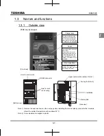
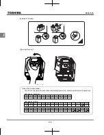
Page 15: ...cidentally touching the terminal block The serial number is recorded on the back side You can lock the door by shutting it an passing a wire key through this hole Note 1 Remove the seal as shown on the next page when installing the inverter side by side with other inverters where the ambient temperature will rise above 40 C Note 2 Some models are wrapped in plastic Hole for control wire RS485 conn...

Page 16: ...on the operation panel uses the following symbols to indicate parameters and operations LED display numbers 0 1 2 3 4 5 6 7 8 9 0 1 2 3 4 5 6 7 8 9 LED display letters Aa Bb C c Dd Ee Ff Gg H h I i Jj Kk Ll a b c w d e f g h k i j l Mm Nn O o Pp Qq Rr Ss Tt Uu Vv Ww Xx Yy Zz m n o x p q r s t u v y ...

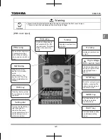
Page 17: ... blinks when operation starts Dispalyed numbers are percents Displayed numbers are in Hertz The internal terminal in the upper right carries a high voltage Never touch it While the runing lamp is blinking pressing this button slows down and stops the inverter Switches between run settings and status monitor modes Switches between easy and standard setting modes While this is lit the inverte r is i...

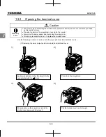
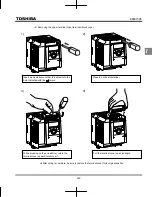
Page 18: ...pply when removing the wiring cover After wiring is complete be sure to replace the terminal cover Use the following procedure to remove both the upper and lower terminal block covers 1 Removing the lower output and dc terminals terminal block cover 1 2 3 4 Insert a screwdriver or other thin object into the hole indicated with the mark Press in on the screwdriver While pressing on the screwdriver ...

Page 19: ... be sure to restore the terminal cover to its original position 1 2 3 4 Insert a screwdriver or other thin object into the hole indicated with the mark Press in on the screwdriver While pressing on the screwdriver rotate the terminal cover upward to remove it Pull the terminal cover up at an angle ...

Page 20: ...erminal NOTE Tightening torque M3 5 xxx 3 5 1 0Nm 8 9lb in M4 xxx 4 1 4Nm 12 4lb in M5 xxx 5 3 0Nm 26 6lb in NOTE xxx means wire sizes For the wire sizes refer to the table in section 10 1 VFNC3 2001 2007P Bend the clips on the wiring port of the terminal cover to connect the PO PA and PC terminals R L1 S L2 T L3 P0 PA PC U T1 V T2 W T3 Grounding terminal M4 screw Short circuit cover EMC plate for...

Page 21: ...the clips on the wiring port of the terminal cover to connect the PO PA and PC terminals VFNC3S 1001 1004P 2001 2007PL R L1 S L2 N P0 PA PC U T1 V T2 W T3 M3 5 screw Grounding capacitor switch 2001 to 2007 PL only Grounding terminal M4 screw M3 5 screw Grounding terminal Short circuit cover EMC plate for installation Note 1 Grounding terminal M5 screw Grounding terminal Bend the clips on the wirin...

Page 22: ... in high attenuation noise filter and are grounded via a capacitor A switch makes for easy switching to reduce leakage current from the inverter and the load on the capacitor However be careful as reducing the load means non conformity with the EMC standard on the inverter itself Always do switching with the power off Pressing this switches the grounding capacitor s capacity from small to large De...

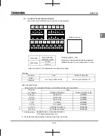
Page 23: ...0506 0 75 18 AI 0 75 6GY DN00706 1 18 AI 1 6RD DN01006 1 5 16 AI 1 5 8BK DN01508 2 X 0 5 AI TWIN2 X 0 5 8WH DTE00508 2 X0 75 AI TWIN2 X 0 75 8GY DTE00708 1 Crimping pliers CRIMPFOX ZA3 PHOENIX CONTACT CT1 Dinkle International Ltd 2 These ferrules enable practical crimping of two wires in a ferrule OUT NO CC F R S1 S2 P24 FLA FLB FLC CC VI P5 FM Optional connector RJ45 RS485 connector Stripping len...

Page 24: ...effect If this happens operate with the output decreased from rated load To carry out low speed operation continuously at the rated torque we recommend to use a inverter rated motor or a forced cooled motor designed for use with an inverter When operating in conjunction with a inverter rated motor you must change the inverter s motor overload protection level to VF motor use Adjusting the overload...

Page 25: ...h backlash When using the inverter in the above combination use the S pattern acceleration deceleration function or when vector control is selected adjust the speed control response or switch to V f control mode Combined with loads that have sharp fluctuations in rotation such as piston movements In this case adjust the response time inertial moment setting during vector control or switch to V f c...

Page 26: ...ed on and off by using low speed signal OUT Refer to section 6 1 1 In some situations such as with elevators turning the brake on and off with a low speed signal may be appropriate Be sure to contact us before designing your system 1 4 2 Inverters Protecting inverters from overcurrent The inverter has an overcurrent protection function The programmed current level is set to the inverter s maximum ...

Page 27: ... more inverters are used on the same power line MCCB1 MCCBn 1 MCCB3 MCCB2 INV1 INV2 INVn circuit breaking fuse Breaking of selected inverter There is no fuse in the inverter s main circuit Thus as the diagram above shows when more than one inverter is used on the same power line you must select interrupting characteristics so that only MCCB2 to MCCBn 1 will trip and the MCCB1 will not trip when a ...

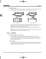
Page 28: ...round capacitor compliant with the EMC directive which gives them a comparatively higher value than a normal inverter Take this into consideration when selecting a leakage breaker Refer to Leakage current E6581181 in the separate user manual for details 2 Influence of leakage current across ground Leakage current may flow not just through the inverter system but also through ground wires to other ...

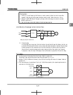
Page 29: ...proportion to the motor rating Remedies 1 Use the electronic thermal built into the inverter Refer to section 3 5 The setting of the electronic thermal is done using parameter 2 Reduce PWM carrier frequency However the motor magnetic noise is increased Refer to section 6 11 3 This can be improved by installing 0 1μ 0 5μF 1000V film capacitor to the input output terminals of each phase in the therm...

Page 30: ... However the motor magnetic noise is increased Refer to section 6 11 3 Use the monitor functions built into the inverter Use the monitor functions on the panel built into the inverter to check current values Refer to section 8 2 1 4 Influence and remedy of the leakage current by long distance wiring Caution Mandatory action As a remedy when using an AC reactor PFL series for the output side of an ...

Page 31: ... electric shock or fire Mandatory action Operate under the environmental conditions prescribed in the instruction manual Operations under any other conditions may result in malfunction Caution Prohibited Do not install the VF nC3 Inverter in any location subject to large amounts of vibration This could cause the unit to fall resulting in bodily injury Mandatory action Check to make sure that the i...

Page 32: ...ment position 5cm Position for measuring ambient temperature Note The inverter is a heat emitting body Make sure proper space and ventilation is provided when installing in the cabinet When installing inside a cabinet we recommend the top seal peeled off although 40 C or less Do not install in any location that is subject to large amounts of vibration Note If the VF nC3 Inverter is installed in a ...

Page 33: ...in injury If braking is necessary to hold motor shaft install a mechanical brake The brake on the inverter will not function as a mechanical hold and if used for that purpose injury may result 1 Normal installation Select an indoor location with good ventilation and then install it upright on a flat metal plate When installing multiple inverters leave at least 5 cm of space between each inverter a...

Page 34: ...loss for the optional external devices input reactor DC reactor radio noise reduction filters etc is not included in the calorific values 2 It is power consumption when power is on but output frequency is 0Hz and cooling fan is activated Voltage class Inverter type Calorific values Note 1 Amount of forcible air cooling ventilation required m 3 min Heat discharge surface area required for sealed st...

Page 35: ...t run them parallel and do not bundle them Provide shielding and twisted wire for control circuit wiring Separate the input power and output motor wires of the main circuit Do not place them in the same conduit do not run them parallel and do not bundle them Ground the inverter grounding terminals Install surge suppressor on any magnetic contactor and relay coils used around the inverter Install n...

Page 36: ...re the ambient temperature will not rise above 40 C When using inverters where the ambient temperature will rise above 40 C leave a space of 3 cm or more between them and remove the caution label from the top of each inverter or operate each inverter at a current lower than the rated one Ensure a space of at least 20 centimeters on the top and bottom of the inverters Install an air deflecting plat...

Page 37: ...nly after attaching the front cover or closing door if enclosed in a cabinet If power is turned on without the terminal cover attached or closing door if enclosed in a cabinet This can result in electric shock or other injury Electrical construction work must be done by a qualified expert Connection of input power by someone who does not have that expert knowledge may result in fire or electric sh...

Page 38: ...es the main circuit to be shut off control power will also be shut off When checking the cause of the malfunction or the trip use the trip holding retention selection parameter Wiring Cover the crimp style terminal with insulated tube or use the crimp style terminal with insulation sleeve when crimp style terminals are used for the main circuit terminals Connect the terminals so that adjacent term...

Page 39: ...ing wires on equipment MCCB that is connected to inverter power side Touching the wires before that time could result in electric shock Do not shut down the external power supply on ahead when VIA terminal is used as logic input terminal by external power supply f127 200 It could cause unexpected result as VIA terminal is ON status Mandatory action Set a parameter f109 when VI terminal is used as ...

Page 40: ... is not provided for single phase models Use the R L1 and S L2 terminal as input terminals 2 The inverter is supplied with the PO and the PA terminals shorted by means of a shorting bar Before installing the DC reactor DCL remove the bar 3 When using the OUT output terminal in sink logic mode short the NO and CC terminals Control circuit I M Frequency meter ammeter Operation panel 5 1ph 120V model...

Page 41: ...horted by means of a shorting bar Before installing the DC reactor DCL remove the bar 3 When using the NO output terminal in source logic mode short the P24 and OUT terminals Noise filter I M Frequency meter ammeter RS485 communication connector Operation panel 2 5 option 5 1ph 120V models cannot be used with DC reactors FLC FLB FLA 6 When external potentiometer is connected by using P5 terminal s...

Page 42: ...e connected 0 R L1 S L2 and T L3 Motor lines are connected to U T1 V T2 and W T3 E Motor Connections with peripheral equipment Motor Power supply Inverter DC reactor Molded case circuit braker R L1 S L2 T L3 PA PO V T2 U T1 W T3 IM Magnetic contactor Input AC reactor Noise reduction filter Zero phase reactor Note 1 The T L3 terminal is not provided for any single phase models So if you are using s...

Page 43: ...function and specification of each terminal please refer to the following table Refer to section 1 3 3 3 about the arrangement of control circuit terminals Control circuit terminals Terminal symbol Input output Function Electrical specifications Inverter internal circuits F Input Multifunction programmable logic input Shorting across F CC causes forward rotation open causes slow down and stop When...

Page 44: ... logic input terminal When using the sink logic be sure to insert a resistor between P24 VI 4 7 k 1 2 W 5V 10Vdc internal impedance 40k 4 20mA internal impedance 250 Note 1 1 6k 5V 250 39 2k 47k 47k ON Current OFF Voltage ON 10V OFF 5V VI CC FM Output Multifunction programmable analog output Standard default setting output frequency The function can be changed to 0 10Vdc voltage or 0 20mAdc 4 20mA...

Page 45: ... to be passed Pulse frequency range 38 1600pps OUT NO 10 FLA FLB FLC Note 2 Output Multifunction programmable relay contact output Detects the operation of the inverter s protection function Contact across FLA FLC is closed and FLB FLC is opened during protection function operation Max switching capacity 250Vac 2A 30Vdc 2A cos 1 at resistive load 250Vac 1A cos 0 4 30Vdc 1A L R 7ms Min permissible ...

Page 46: ...ower supply and its connections vary depending on the power supply used Setting of sink source logic varies depending on the setup menu setting Refer to section 11 5 Sink source logic can be switched by parameter Examples of connections when the inverter s internal power supply is used CC NO Source Positive logic Inverter P24 F Programmable controller Common Common Output Input Input 24VDC Output ...

Page 47: ...d CC terminal of the inverter P24 CC Note 4 24VDC F Output 24VDC OUT NO Input Inverter Programmable controller P24 Common 24VDC OFF f127 200 CC F 24VDC Output Inverter 24VDC ON f127 100 24VDC OUT NO Input Programmable controller Input Input Output Common Common Output Common Source Positive logic f127 100 Sink Negative logic f127 200 ...

Page 48: ...se of sink logic between VI and CC terminals in case of source logic Recommended resistance 4 7k 1 2W When using VI terminal as a logic input terminal set the parameter and connect as following schematics If no resistor is inserted logic input will be left always ON which is very dangerous Switch between analog input and logic input before connecting the terminals to the control circuit terminals ...

Page 49: ...ion in such a state the result may be fire Contact your Toshiba distributor for repairs Always turn power off if the inverter is not used for long periods of time Turn the input power on only after attaching the terminal block cover When enclosed inside a cabinet and used with the terminal block cover removed always close the cabinet doors first and then turn the power on If the power is turned on...

Page 50: ...cy of the motor connected See the table on the following page Follow these steps to change the setup menu Example Selecting a region code to Panel operated LED display Operation Power on set is blinking Turn the setting dial and select region code Europe Press the center of the setting dial to determine the region The output frequency is displayed Standby When changing the region selected in the s...

Page 51: ... settings 50 0 Hz 60 0 Hz 50 0 Hz 60 0 Hz VI input point 2 frequency 50 0 Hz 60 0 Hz 50 0 Hz 60 0 Hz Base frequency voltage 1 2 230 V 230 V 230 V 200 V Sink source switching Supply voltage correction output voltage limitation 2 2 2 3 Motor rated speed 1410 min 1 1710 min 1 1410 min 1 1710 min 1 F R S1 S2 CC 0 Sink logic Negative common Common CC F R S1 S2 P24 100 Source logic Positive common Commo...

Page 52: ...l board 0 5V 0 10Vdc 4 20mAdc Use the basic parameters command mode selection and frequency setting mode selection for selection Parameter setting Title Function Adjustment range Default setting Command mode selection 0 Terminal board 1 Panel keypad including extension panel 2 RS485 communication 1 Frequency setting mode selection 0 Terminal board VI 1 Setting dial 1 press in center to save 2 Sett...

Page 53: ...value are displayed alternately 1 Run and stop using the panel keypad Use the and keys on the panel keypad to start and stop the motor Motor runs Motor stops The direction of rotation is determined by the setting of parameter forward run reverse run selection forward run reverse run Forward run and reverse run are switchable with the extension panel option Set the parameter fr forward run reverse ...

Page 54: ... Setting using the keypad or extension panel option or Moves the frequency up Moves the frequency down For an extension panel option key moves the frequency up key moves the frequency down Example of operating from the panel press in center to save Panel operation LED display Operation Displays the output frequency When standard monitor display selection Output frequency Set the frequency command ...

Page 55: ...ve even if power is off Panel operation LED display Operation Displays the output frequency When standard monitor display selection Output frequency Set the frequency command value The frequency will be saved even if the power is turned off in this state ...

Page 56: ...otentiometer 1 10k 1 4W Refer to section 6 5 2 for detailed adjustment Frequency 0 MIN MAX P5 CC V I Note Set parameter Voltage signal Setting frequency using voltage signals 0 10V Refer to section 6 5 2 for detailed adjustment Note Set parameter CC V I Voltage signal 0 10Vdc Frequency 50 or 60Hz 0 0Vdc 10Vdc 50 or 60Hz Frequency 50 or 60Hz 0 4mAdc 20mAdc CC V I Current signal 4 20mAdc CC V I Volt...

Page 57: ...2 Parameter setting default setting Title Function Programmed value Command mode selection 1 Frequency setting mode selection 2 3 Operation Run stop Press the and keys on the panel Frequency setting Turn the setting dial to set the frequency The frequency setting is saved just by turning the setting dial Motor IM R L1 S L2 T L3 U T1 V T2 W T3 PO PC PA Operation panel Ex 1 RUN STOP ...

Page 58: ...election 1 Frequency setting mode selection 1 3 Operation Run stop Press the and keys on the panel Frequency setting Turn the setting dial to set the frequency To save the frequency setting press the center of the setting dial and the set frequency will flash on and off alternately Motor IM R L1 S L2 T L3 U T1 V T2 W T3 PO PC PA Operation panel Ex 2 RUN STOP ...

Page 59: ...n Programmed value Command mode selection 0 Frequency setting mode selection 1 or 2 3 Operation Run stop ON OFF input to F CC R CC with sink logic Frequency setting Turn the setting dial to set the frequency Motor IM F R L1 S L2 T L3 U T1 V T2 W T3 Forward signal R CC PO PC PA Reverse signal Common MCCB Operation panel Ex 3 ...

Page 60: ...c external potentiometer or 4 20mAdc to set the frequency Set the voltage current input of VI in parameter 0 Voltage signal input 0 10V 1 Current signal input 4 20mA 3 Voltage signal input 0 5V when the P5 terminal is connected and the external potentiometer is used Motor IM F R L1 S L2 T L3 U T1 V T2 W T3 Forward signal R PO PC PA Reverse signal MCCB CC VI Common Current signal 4 20mA CC VI PP Vo...

Page 61: ...tion output at f sl 17 Default setting Meter selection 0 Output frequency 1 Output current 2 Frequency command value 3 Input voltage DC detection 4 Output voltage command value 5 to 11 12 Stator frequency 13 VI input value 14 15 Fixed output 1 output current 100 equivalent 16 Fixed output 2 output current 50 equivalent 17 Fixed output 3 other than the output current 18 RS485 communication data 19 ...

Page 62: ... less than 750Ω Use at over 1kΩ external load resistance if used for voltage output Note 2 is the motor drive frequency Adjustment scale with parameter Meter adjustment Connect meters as shown below FM CC Meter Frequency meter default setting VF nC3 FM CC VF nC3 The reading of the frequency meter will fluctuate during scale adjustment Meter ammeter The reading of the ammeter will fluctuate during ...

Page 63: ...state Adjustment of output current 1 If when adjusting the meter for output current there are large fluctuations in data during adjustment making adjustment difficult the meter can be adjusted in inverter stop state When setting to for fixed output 1 output current 100 equivalent a signal of absolute values will be output inverter s rated current 100 In this state adjust the meter with the Meter a...

Page 64: ...1 100 Electronic thermal protection characteristic selection Setting value Overload protection Overload stall 0 0 Standard motor valid invalid 1 valid valid 2 invalid invalid 3 invalid valid 4 VF motor special motor valid invalid 5 valid valid 6 invalid invalid 7 invalid valid f173 Motor electronic thermal protection level 2 10 100 A 1 100 f607 Motor 150 overload detection time 10 2400 s 300 Elect...

Page 65: ...ent Note Do not use the overload stall function with loads having constant torque characteristics such as conveyor belts in which load current is fixed with no relation to speed Using standard motors other than motors intended for use with inverters When a motor is used in the lower frequency range than the rated frequency that will decrease the cooling effects for the motor This speeds up the sta...

Page 66: ...urn the setting dial to change the parameter to motor rated current inverter output rated current 100 2 0 4 2 100 Press the center of the setting dial to save the changed parameter and the parameter are displayed alternately Note The rated output current of the inverter should be calculated from the rated current for frequencies below 4kHz regardless of the setting of the PWM carrier frequency par...

Page 67: ...reduction is fixed at 6 Hz 6Hz 0 6 2 Motor 150 overload time f607 Parameter f607 is used to set the time elapsed before the motor trips under a load of 150 overload trip 2 within a range of 10 to 2400 seconds 3 Inverter overload characteristics Set to protect the inverter itself The setting of this parameter cannot be turned to off When an inverter overload trip operates operation can be improved ...

Page 68: ...rter 4 Electronic thermal memory f632 When the power is OFF it is possible to reset or maintain the overload totaling level This parameter s settings are applied both to the motor s electronic thermal memory and the electronic thermal memory for inverter protection Parameters settings Title Function Adjustment range Default setting Electronic thermal memory 0 Disabled 1 Enabled is a function for c...

Page 69: ...ge Setting Command mode selection 0 Terminal board 1 Panel keypad including extension panel 2 RS485 communication 0 Note When switching between preset speed operation and other speed commands analog signal setting dial communication etc select the frequency setting mode at Refer to section 3 or 5 5 2 Preset speed frequency setting Set the speed frequency of the number of steps necessary Parameter ...

Page 70: ... Terminal R Input terminal function selection 2A R 14 Preset speed command 3 SS3 Terminal VI Analog logic input selection VI 2 logic input Input terminal function selection 5 VI 16 preset speed command 4 SS4 In the default settings SS3 and SS4 are not assigned Assign SS3 and SS4 to R and VI with input terminal function selection VI terminal must also be set for switching to logic input 1 When VI t...

Page 71: ...center to record 2 Setting dial 3 RS485 communication Preset speed command Active Preset speed command valid Note Terminal command valid Setting dial command valid Communication command valid Inactive Terminal command valid Setting dial command valid Communication command valid Note The preset speed command is always given priority when other speed commands are input at the same time An example of...

Page 72: ...d Parameters can be registered as necessary max 24 parameters Standard setting mode Both basic and extended all parameters are displayed Each press of the EASY key switches between the Easy setting mode and the Standard setting mode This mode is for monitoring the output frequency and setting the frequency reference value If also displays information about status alarms during running and trips Di...

Page 73: ...fer to chapter 8 The inverter can be moved through each of the modes by pressing the MODE key y y y y Setting monitor mode Status monitor mode Standard monitor mode At power source on MODE MODE MODE RUN MON PRG PRG Frequency setting method Refer to section 3 2 2 How to search and set parameters Refer to section 4 2 Monitoring of operation status Refer to section 8 2 ...

Page 74: ...lamp blinks If the EASY key is pressed while the setting dial is being turned values continue to be incremented or decremented even if you release your finger from the setting dial This feature is handy when setting large values Note Of the available parameters number value parameters etc are reflected in actual operation when the setting dial is turned Note however that the center of the setting ...

Page 75: ...displayed Basic parameters This parameter is a basic parameter for the operation of the inverter Refer to chapter 5 for details Refer to chapter 11 for parameter tables Extended parameters The parameters for detailed and special setting Refer to chapter 6 for details Refer to chapter 11 for parameter tables Note Refer to section 11 8 for unchangeable parameters in running ...

Page 76: ...to the Standard setting mode press the EASY key in the Standard monitor mode is displayed and the mode is switched y Standard monitor mode 1 3 2 4 Parameter title and the setting value are displayed alternately Registered parameters Max 24 parameters MODE MODE Basic parameter setting Easy setting mode Default registered parameters Title Function Command mode selection Frequency setting mode select...

Page 77: ... mode is selected How to set basic parameters 1 Selects parameter to be changed Turn the setting dial 2 Reads the programmed parameter setting Press the center of the setting dial 3 Change the parameter value Turn the setting dial 4 Press this key to save the change Press the center of the setting dial To switch to the Easy setting mode press the EASY key in the Standard monitor mode easy is displ...

Page 78: ...o be selected or set in advance Changed parameters history search History function This function automatically searches for the last five parameters whose settings have been changed To use this function select the parameter Any changes are displayed regardless of whether or not they are the same as standard defaults Refer to section 5 1 for details Set parameters by purpose Guidance function Only ...

Page 79: ...on select the parameter Refer to section 4 3 1 for details 4 3 1 Searching for and resetting changed parameters Automatic edit function Note 1 If you reset a parameter to its factory default the parameter will no longer appear in Note 2 It may take several seconds to display changed parameters because all data stored in the user parameter group is checked against the factory default settings To ca...

Page 80: ...verse direction Press the center of the setting dial to display set values Turn the setting dial and change set values Press the center of the setting dial to set values The parameter name and set value light alternately and are written Use the same steps as those above and turn the setting dial to display parameters to search for or whose settings must be changed and check or change the parameter...

Page 81: ...unction will be displayed as 0 during reading on the right This previous setting is displayed on the left Example cannot be set during the inverter operating Always stop the inverter first and then program Programmed value 50 Hz default setting Setting to sets the following parameters for base frequency 50 Hz use The setting values of other parameters are not changed Max frequency 50Hz Upper limit...

Page 82: ...or you can use parameters as your own default parameters Cumulative fan operation time record clear Setting to resets the cumulative operation time to the initial value zero Set this parameter when replacing the cooling fan and so on Default setting 2 1 Set to to return all parameters to their default settings When is set is displayed for a short time after the settings are configured and then dis...

Page 83: ...layed Content of region settings The number displayed when parameter is read indicates which of the following regions was selected on the setup menu Japan is selected on the setup menu North America is selected on the setup menu Asia Oceania is selected on the setup menu Europe is selected on the setup menu The setup menu is started by writing Refer to section 3 1 for details Note to set to parame...

Page 84: ...ed parameters maximum of 24 types Standard setting mode Standard setting mode in which all parameters are read out How to read out parameters To enter the setting monitor mode switch to the setting monitor mode using the EASY key and then press the MODE key Turn the setting dial to read the parameter The relation between the parameter and the mode selected is shown below When the power is turned o...

Page 85: ... setting mode parameter 7 No function Easy setting mode parameter 8 Easy setting mode parameter 9 Easy setting mode parameter 10 Easy setting mode parameter 11 Easy setting mode parameter 12 Easy setting mode parameter 13 Easy setting mode parameter 14 Easy setting mode parameter 15 Easy setting mode parameter 16 Easy setting mode parameter 17 Easy setting mode parameter 18 Easy setting mode param...

Page 86: ...d and are added respectively to the first and last parameters in a history of changes How to use the history function Operation panel action LED display Operation Displays the output frequency operation stopped When standard monitor display selection Output frequency The first basic parameter history function is displayed The parameter that was set or changed last is displayed Press the center of ...

Page 87: ...e Function Adjustment range Default setting Guidance function 0 1 Note 1 2 Preset speed guidance 3 Analog signal operation guidance 4 Motor 1 2 switching operation guidance 5 Motor constant setting guidance 0 Note 1 is for manufacturer s settings Do not change the settings MODE MODE MODE Guidance function The guidance function refers to the special function of calling up only functions necessary t...

Page 88: ...tting value Press the center of the setting dial to display the purpose specific guidance parameter group refer to table below After moving to the purpose specific guidance parameter group use the setting dial to change the parameters is dialyzed on completion of the setting of the guidance parameter group Display of parameter Press the MODE key to exit the guidance parameter group By pressing the...

Page 89: ...le of parameters that can be changed using the guidance function Preset speed setting guidance auf 2 Analog input operation guidance auf 3 Motor 2 switching operation guidance auf 4 Motor constant setting guidance auf 5 ...

Page 90: ...celeration 0 Disabled manual setting 1 Automatic 2 Automatic only at acceleration 0 When automatically setting acceleration deceleration time always change the acceleration deceleration time so that it conforms to the load For inverters that require a fixed acceleration deceleration time use the manual settings Setting acceleration deceleration time in conformance with mean load allows optimum set...

Page 91: ...deceleration command function number 122 123 to any logic input terminal it can be changed automatic deceleration by compulsion 5 3 2 Manually setting acceleration deceleration time Acceleration time 1 Deceleration time 1 Function 1 For acceleration time 1 programs the time that it takes for the inverter output frequency to go from 0 0Hz to maximum frequency 2 For deceleration time 1 programs the ...

Page 92: ...Parameter setting Title Function Adjustment range Default setting Torque boost setting macro function 0 1 Automatic torque boost auto tuning 2 Vector control auto tuning 3 Energy saving auto tuning 0 Note Parameter displays on the right always return to after setting The previous setting is displayed on the left Ex 1 Increasing torque automatically according to the load is set to Automatic torque ...

Page 93: ...cally programs to 3 Energy saving operation is set to Energy saving auto tuning When torque boost setting macro function control is set to energy saving auto tuning the inverter always passes a current appropriate to the load for energy saving Note 1 The same characteristic can be obtained by setting the V F control mode selection parameter to automatic energy saving and the auto tuning parameter ...

Page 94: ... boost auto tuning Automatic torque boost Auto tuning executed after execution 0 Vector control auto tuning Vector control Auto tuning executed after execution 0 Energy saving auto tuning Energy saving Auto tuning executed after execution 0 4 Increasing torque manually V F constant control This is the setting of constant torque characteristics that are suited for such things as conveyors It can al...

Page 95: ...eypad to run and stop Operation can also be done from the extension panel RS485 communication Run stop operations by RS485 communication from an external device Refer to section 6 19 There are two types of function the function that conforms to commands selected by and the function that conforms only to commands from the terminal board function number 108 109 See the table of input terminal functi...

Page 96: ...nput Frequencies are set by up down commands from a terminal Refer to section 6 5 3 The control input terminal in which the following functions are set is always valid regardless of the setting of and Reset valid only for tripping Standby External input tripping stop command Coast stop command terminal To make changes in the command mode selection and the frequency setting mode selection 1 first s...

Page 97: ... External logic Up down Setting dial 1 RS 485 communications Setting dial 2 Up down key Key valid when f732 0 LOC REM Command mode selection Terminal block Terminal VI Frequency setting mode selection RS 485 communications Terminal block active FMTB Input terminal function 106 107 Panel RUN STOP key Terminal block active CMTB Input terminal function 108 109 RS485 communication priority clear SCLC ...

Page 98: ...es the direction of rotation from forward to reverse after displaying the message Pressing the FWD REV key again changes the direction of rotation from reverse to forward after displaying the message Using extension panel RKP002Z option When is set to and the standard monitor is displayed pressing the DOWN key while pressing the ENT key changes the direction of rotation from forward to reverse aft...

Page 99: ...alues 2 This frequency is used as the reference for acceleration deceleration time Output frequency Hz When 80Hz When 60Hz 80Hz 60Hz 0 100 Frequency setting signal This function determines the value in line with the ratings of the motor and load Maximum frequency cannot be adjusted during operation To adjust first stop the inverter If is increased adjust the upper limit frequency as necessary Para...

Page 100: ...and frequency Hz Command frequency Hz Parameter setting Title Function Adjustment range Default setting Upper limit frequency 0 5 Hz Lower limit frequency 0 0 Hz 0 0 Default setting values vary depending on the setup menu setting Refer to section 11 5 Note1 Do not set a value 10 times larger than base frequency 1 and base frequency 2 for If a large number is set the output frequency can only be ou...

Page 101: ...r the base frequency Note This is an important parameter that determines the constant torque control area Output voltage V Base frequency voltage Output frequency Hz 0 Parameter setting Title Function Adjustment range Default setting Base frequency 1 20 0 400 0 Hz Base frequency voltage1 50 330 V Default setting values vary depending on the setup menu setting Refer to section 11 5 ...

Page 102: ...l when switching to the second motor regardless of the setting Steps in setting are as follows In this example the V F control mode selection parameter is set to Vector control Setting V F control mode selection to 3 sensorless vector control Operation panel action LED display Operation Displays the output frequency Perform during operation stopped When standard monitor display selection Output fr...

Page 103: ... constant This is applied to loads with equipment like conveyors and cranes that require the same torque at low speeds as at rated speeds Output voltage Base frequency voltage Output frequency Hz Base frequency 0 To increase the torque further increase the setting value of the manual torque boost Refer to section 5 12 for details 2 Setting for fans and pumps Setting of V F control mode selection t...

Page 104: ...cording to the motor s name plate Base frequency 1 Base frequency voltage 1 Motor rated capacity Motor rated current Motor rated speed There are three procedures for setting the other motor constants 1 Auto torque boost and a motor constant auto tuning can be set at once To do so set the basic parameter to Refer to section 5 4 1 for details 2 The motor constant can be automatically set auto tuning...

Page 105: ...ter there is no need to set the motor constant In any other case set the following parameters according to the motor s name plate Base frequency 1 Base frequency voltage 1 Motor rated capacity Motor rated current Motor rated speed There are three procedures for setting the other motor constants 1 Automatic energy saving operation and a motor constant can be set at once Set the basic parameter to R...

Page 106: ...When a reactor is connected between the inverter and a motor the motor s generated torque may fall Setting auto tuning may also cause a trip rendering sensorless vector control unusable 5 12 Manual torque boost increasing torque boost at low speeds Torque boost 1 Function If torque is inadequate at low speeds increase torque by raising the torque boost rate with this parameter Output voltage V Bas...

Page 107: ...ils 5 14 Preset speed operation speeds in 15 steps s Preset speed frequency 1 7 Refer to section 3 6 for details 5 15 Standard default setting t Default setting Refer to section 4 3 2 for details 5 16 Checking the region setting selection Checking the region setting Refer to section 4 4 for details 5 17 EASY key mode selection EASY key mode selection Refer to section 4 5 for details ...

Page 108: ...tic brake excitation release signal Refer to Motors with a brake in section 1 4 1 for application This signal can also be used as an operation signal when is set to 0 0Hz because an ON signal is put out if the inverter is in output state Output from the open collector output terminal OUT Default Output from relay output FLA FLB FLC is possible depending on the parameter settings Parameter setting ...

Page 109: ... output to FLA FLC FLB terminals 6 1 2 Output of designated frequency reach signal Speed reach detection band Function When the output frequency becomes equal to the setting by designated frequency an ON or OFF signal is generated Parameter setting Parameter setting of designated frequency and detection band Title Function Adjustment range Default setting Speed reach detection band 0 0 Hz 2 5 Para...

Page 110: ...tput frequency becomes equal to the frequency set by an ON or OFF signal is generated Parameter setting Parameter setting of frequency and detection band Title Function Adjustment range Default setting Speed reach setting frequency 0 0 Hz 0 0 Speed reach detection band 0 0 Hz 2 5 Parameter setting of output terminal selection Title Function Adjustment range Setting Output terminal selection 1A OUT...

Page 111: ... 6 2 Input signal selection 6 2 1 Priority selection Both F and R are ON Priority selection Both F and R are ON Function This parameter allows you to select the direction in which the motor runs when a forward run F command and a reverse run R command are entered simultaneously 1 Reverse 2 Slowdown stop Parameter setting Title Function Adjustment range Default setting Priority selection Both F and...

Page 112: ... Forward run Reverse run Forward run command Reverse run command ON OFF ON OFF 0 Setting frequency Setting frequency Time s 2 Stop If an F command and an R command are entered simultaneously the motor will slow down to a stop Forward run Reverse run Forward run command Reverse run command ON OFF ON OFF Output frequency Hz Setting frequency Time s 0 ...

Page 113: ...election VI terminal 0 Voltage signal input 0 10V 1 Current signal input 4 20mA 2 Logic input 3 Voltage signal input 0 5V 0 Resolution is maximum 1 1000 when VI terminal is used as analog input terminal In sink logic connection be sure to insert a resistor between the P24 terminal and the VI terminal when using it as the logic input terminal Refer to section 2 3 2 for details page B 11 For informa...

Page 114: ... selecting them on the setup menu the parameters are used for switching sink source However disconnect the control circuit terminals of the inverter Otherwise the equipment may malfunction After setting switching the check alarms are displayed reset panel external signal or power Refer to pages B 10 and B 11 regarding sink source logic connections 6 3 2 Keeping an input terminal function always ac...

Page 115: ...terminal selection 2A R Input terminal selection 3A S1 Input terminal selection 4A S2 Analog logic input selection VI Terminal Input terminal selection 5 VI Input terminal selection 1B F Input terminal selection 2B R Input terminal selection 3B S1 Input terminal selection 4B S2 Input terminal selection 1C F Input terminal selection 2C R Refer to section 7 2 1 for details about input terminal funct...

Page 116: ...ection parameter is enabled only for motor1 If motor 2 is selected V F control will be given constant torque characteristics Parameter setting Title Function Adjustment range Default setting Base frequency 2 25 0 400 0 Hz 1 Base frequency voltage 2 50 330 V 1 Torque boost value 2 0 0 30 0 Depending on model Refer to section 11 4 Motor electronic thermal protection level 2 10 100 A 2 100 Stall prev...

Page 117: ... OFF ON OFF V F constant OFF OFF ON Note 1 Each of the following numbers 25 29 33 are reverse signals Note 2 pt and V F constant cannot be switched while running Stop the motor before switching After the change please drive after 0 2 seconds or more vl and f170 vlv and f171 vb and f172 can be switched while running Note 3 Integral value of motor electronic thermal is cleared after the motor switch...

Page 118: ...witching frequency command Frequency setting mode selection Input terminal selection 1A 2A 3A 4A 5 Input terminal selection 1B 2B 3B 4B 1C 2C Function Frequency command can be changed according to the terminal block input Refer to section 5 5 for details ...

Page 119: ...e done because noise effects stability To fine adjust the frequency command characteristics for VI input use the parameters f470 and f471 Refer to section 6 5 4 Parameter setting Title Function Adjustment range Default setting Analog logic input selection VI terminal 0 Voltage signal input 0 10V 1 Current signal input 4 20mA 2 Logic input 3 Voltage signal input 0 5V 0 VI point 1 setting 0 100 0 VI...

Page 120: ...A VI terminal Point settings adjust the frequency command for the voltage input Gradient and bias can be set easily 100 10V voltage signal 0 Hz 0 0 50 60 Hz Frequency commnd Voltage input 0 10V VI terminal When the external potentiometer is used it is so that the frequency set in output In case of the voltage signal 0 5Vdc when output frequency does not match the value set in please adjust or Refe...

Page 121: ... 0 Hz 0 1 External logic input DOWN response time 0 0 10 0 S 0 1 External logic input DOWN frequency steps 0 0 Hz 0 1 Initial value of UP DOWN frequency Hz 0 0 Change of the initial value of UP DOWN frequency 0 Not changed 1 Setting of changed when power is turned off 1 This function is valid when the parameter frequency setting mode selection is set Input terminal settings Assign the following fu...

Page 122: ... Gradient f267 f266 Gradient f265 f264 Upper limit frequency DOWN signal UP signal Forward reverse command Set frequency clearing signal Note If the operation frequency is set to the lower limit frequency it will increase from 0Hz when power is turned on for the first time after the setting and therefore the output frequency will not rise until the operation frequency reaches the lower limit frequ...

Page 123: ... automatically save the frequency immediately before it is turned off and start operation at that frequency next time power is turned on set change of initial up down frequency to 1 which changes the setting of when power is turned off Keep in mind that the setting of is changed each time power is turned off Frequency adjustment range The frequency can be set from 0 0Hz to Maximum frequency The lo...

Page 124: ...To give leeway the inverter is factory adjusted by default so that it will not produce an output until a certain amount of voltage is applied to the VI input terminal If you want to reduce the leeway set f470 to a larger value Note that specifying a too large value may cause an output frequency to be output even though the operation frequency is 0 zero Hz Gain adjustment of VI input terminal f471 ...

Page 125: ...below the rated slippage of the motor Parameter setting Title Function Adjustment range Default setting Starting frequency 0 1 10 0 Hz 0 5 6 6 2 Run stop control with frequency setting signals Operation starting frequency Operation starting frequency hysteresis Function The Run stop of operation can be controlled simply with frequency setting signals Parameter setting Title Function Adjustment ran...

Page 126: ...ency DC braking current DC braking time Output frequency Hz DC braking Operation signal F CC ON OFF Output current A 0 0 Set frequency Note1 During DC braking the overload protection sensitivity of the inverter increases The DC braking current may be adjusted automatically to prevent tripping Note 2 During DC braking the carrier frequency becomes the setting of parameter f300 PWM carrier frequency...

Page 127: ... a stop At that time is displayed alternately on the operation panel This function will be canceled if a frequency command above the lower limit frequency Hz Parameter setting Title Function Adjustment range Default setting Time limit for lower limit frequency operation 0 0 Disabled 0 1 600 0 s 0 0 Hysteresis for lower limit frequency operation 0 0 Hz 0 2 Note This function is valid when doing for...

Page 128: ...eresis characteristics with respect to the jump frequency are given to the motor Jump width Jump frequency Output frequency Hz Frequency setting signal 0 Parameter setting Title Function Adjustment range Default setting Jump frequency 0 0 Hz 0 0 Jump width 0 0 30 0 Hz 0 0 Note 1 During acceleration and deceleration the operation frequency jumps do not occur 6 10 Preset speed frequencies Preset spe...

Page 129: ...rying out the trip by oh overheat or ol3 main module overload the carrier frequency is reduced automatically and the trip can be avoided However the magnetic noise from the motor is increased Parameter setting Title Function Adjustment range Default setting PWM carrier frequency 2 16 kHz 12 Random mode 0 Disabled 1 Automatic setting 0 Carrier frequency control mode selection 0 Carrier frequency wi...

Page 130: ... 50 60 C 1 2 A 1 0 A 1 0 A 2004PL 50 C or less 2 4 A 2 4 A 2 4 A Above 50 60 C 2 0 A 1 8 A 1 8 A 2007PL 50 C or less 4 2 A 3 2 A 2 8 A Above 50 60 C 3 6 A 2 5 A 2 2 A 2015PL 40 C or less 7 5 A 7 5 A 7 1 A Above 40 50 C 7 5 A 7 1 A 7 1 A Above 50 60 C 7 1 A 7 1 A 6 6 A 2022PL 40 C or less 10 0 A 9 1 A 8 0 A Above 40 50 C 10 0 A 7 5 A 7 5 A Above 50 60 C 7 5 A 7 5 A 7 0 A Single phase 100 V class VF...

Page 131: ...power has been restored restarts the motor smoothly motor speed search function This parameter also allows commercial power operation to be switched to inverter operation without stopping the motor During operation is displayed The acoustic noise of the motor could be increased Parameter setting Title Function Adjustment range Default setting Auto restart control selection 0 Disabled 1 At auto res...

Page 132: ...see the number of revolutions of the motor For this reason the start up takes more time than usual Use this function when operating a system with one motor connected to one inverter This function may not operate properly in a system configuration with multiple motors connected to one inverter In case of using this function do not set the output phase failure detection selection f605 1 2 Applicatio...

Page 133: ...tting Title Function Adjustment range Default setting f302 Regenerative power ride through control Deceleration stop 0 Disabled 1 Regenerative power ride through control 2 Deceleration stop during power failure 0 Note 2 Even if these functions are used a motor may coast according to load conditions In this case use the auto restart function f301 for the smooth restart after power supply is restore...

Page 134: ...the voltage in main circuit falls below main circuit undervoltage moff level at operation deceleration stop during power failure the motor will coast and inverter displays stop and 0 0 alternately The motor continues coasting even after power supply is restored Motor speed Input voltage Note 5 If momentary power failure occurs during deceleration stop power ride through control will not be perform...

Page 135: ...entary power failure overcurrent overvoltage or overload This function will also be canceled if retrying is not successful within the specified number of times Retry is only done when the following trips occur Protective operation detection relay signals FLA FLB FLC terminal signals are not sent during use of the retry function Default setting To allow a signal to be sent to the protective action ...

Page 136: ...on 0 Enabled 1 Disabled 2 Enabled Quick deceleration control 3 Enabled Dynamic quick deceleration control 2 If is set to 2 quick deceleration control the inverter will increase the voltage to the motor over excitation control to increase the amount of energy consumed by the motor when the voltage reaches the overvoltage protection level and therefore the motor can be decelerated more quickly than ...

Page 137: ...equency voltage1 50 330 V 1 Supply voltage correction output voltage limitation 0 Supply voltage uncorrected output voltage limited 1 Supply voltage corrected output voltage limited 2 Supply voltage uncorrected output voltage unlimited 3 Supply voltage corrected output voltage unlimited 1 1 Default setting values vary depending on the setup menu setting Refer to section 11 5 For supply voltage unc...

Page 138: ...tion no output voltage limit Voltage compensation no output voltage limited Input voltage High Low Output frequency Output voltage V 0 Input voltage The above applies when V F control mode selection parameter is set to or 1 the output voltage can be prevented from exceeding the input voltage Rated voltage Input voltage High Low Output voltage V Output frequency 0 Note that even if the input voltag...

Page 139: ...gain Integral gain Differential gain PID forward reverse characteristics selection Function Using feedback signals 4 to 20mA 0 to 5 V 0 to 10V from a detector process control can be exercised for example to keep the airflow amount of flow or pressure constant Or it is also possible to always set 0 for integral and differential at terminal input Parameter setting Title Function Adjustment range Def...

Page 140: ...Logic input 3 Setting PID control Set PID control 1 Enabled 1 Set Acceleration time and Deceleration time to the system fitting values 2 To limit the output frequency set parameters Upper limit frequency and Lower limit frequency If PID set value are set with the setting dial however the process quantity setting range will be limited by the settings of and Note 3 Assigning the terminal function nu...

Page 141: ...ng A larger P gain adjustment value gives faster response Too large an adjustment value however results in an unstable event such as hunting I gain adjustment parameter This parameter adjusts the integral gain level during PID control Any deviations remaining unremoved during proportional action are cleared to zero residual deviation offset function A larger I gain adjustment value reduces residua...

Page 142: ...tting as required Refer to section 6 5 2 for details Example of 0 10 Vdc voltage input setting Example of 0 5 Vdc voltage input setting Example of 4 20 mAdc current input setting 6 Setting the time elapsed before PID control starts You can specify a waiting time for PID control to prevent the inverter from starting PID control before the control system becomes stable for example after start up The...

Page 143: ...on 1 Reverse When characteristic is reversed using logic input terminal Assign the terminal function number 54 55 PID characteristics switching to an input terminal Caution If reverse characteristics is selected for and terminal input at the same time they become forward characteristic PID set value Feedback value 1 PID Output Opposite Original characteristic Characteristic selection parameter or ...

Page 144: ...ndently 3 Combining the V F control mode selection and manual tuning Caution If the settings for V F control mode selections are automatic torque boost control vector control energy saving Look at the motor s name plate and set the following parameters Base frequency 1 rated frequency Base frequency voltage 1 rated voltage Motor rated capacity Motor rated current Motor rated speed Set the other mo...

Page 145: ...he motor will trip with the dis play of and no constants will be set for that motor 4 High speed motors high slip motors or other special motors cannot be auto tuned For these motors perform manual tuning using Selection 3 described below 5 Provide cranes and hoists with sufficient circuit protection such as mechanical braking Without sufficient circuit protection the resulting insufficient motor ...

Page 146: ...e motor s test report by the rated current Increasing this value increases the excitation current Set the rated rotational speed of the motor For the rated current see the motor s nameplate or test report Adjustment method for the moment of inertia of the load Adjusts the excess response speed A larger value gives a smaller overshoot at the acceleration deceleration completion point In the default...

Page 147: ...le Function Adjustment range Default setting Acceleration time 2 0 0 3000 s 10 0 Deceleration time 2 0 0 3000 s 10 0 1 Switching according to frequency automatically switching from the set frequency to the acceleration deceleration time Parameter setting Title Function Adjustment range Default setting Acceleration deceleration 1 2 switching frequency 0 0 disabled 0 1 0 0 3 Acceleration at ramp of ...

Page 148: ...erminal block b Set the second acceleration deceleration switching to any input terminal The following shows an example of setting to input terminal S2 Title Function Adjustment range Setting Input terminal selection 4A S2 0 201 24 AD2 2nd acceleration deceleration Setting value 25 is reverse signal 6 15 2 Acceleration deceleration pattern setting Acceleration deceleration 1 pattern Acceleration d...

Page 149: ...ual acceleration time Max frequency Set frequency Time s Output frequency Hz 0 Actual deceleration time Max frequency Set frequency Time s Output frequency Hz 0 3 S pattern acceleration deceleration 2 Motor acceleration torque increases slowly in areas with a small weak magnetic field Perfect for operation of high speed spindles Output frequency Hz Max frequency Time s 0 Max frequency Set frequenc...

Page 150: ...detection time 10 2400 s 300 f632 Electrical thermal memory 0 Disabled 1 Enabled 0 Refer to section 3 5 for details Note The 100 standard value is the rated output current indicated on the nameplate 6 16 2 Setting of stall prevention level Stall prevention level 1 Stall prevention level 2 Caution Prohibited Do not set the stall prevention level extremely low If the stall prevention level parameter...

Page 151: ...nameplate 6 16 3 Inverter trip retention Inverter trip retention selection Function If the inverter trips this parameter will retain the corresponding trip information Trip information that has thus been stored into memory can be displayed even after power has been reset Parameter setting Title Function Adjustment range Default setting Inverter trip retention selection 0 Cleared with power off 1 R...

Page 152: ...l FL operates Also when is set to emergency DC braking stop set DC braking amount and DC braking time 1 Emergency stop from terminal Emergency stop occurs at contact a or b Follow the procedure below to assign a function to an input terminal and select a stop method Parameter setting Title Function Adjustment range Default setting Emergency stop selection 0 Coast stop 1 Slowdown stop 2 Emergency D...

Page 153: ... or more the tripping function and the FL relay will be activated At the same time a trip information will also be displayed Set to to open the motor inverter connection by switching commercial power operation to inverter operation Detection errors may occur for special motors such as high speed motors No tripping FL relay deactivated With the power on the phase failure detection is enabled only a...

Page 154: ...ction Adjustment range Default setting Input phase failure detection selection 0 Disabled 1 Enabled 1 Note1 Setting to input phase failure detection disabled may result in a breakage of the capacitor in the inverter main circuit if operation is continued under a heavy load in spite of the occurrence of an input phase failure Note2 Parameter f608 is invalid for single phase input model Note3 When o...

Page 155: ...al remains ON 6 16 8 Detection of output short circuit Detection of output short circuit at start up Function This parameter detects inverter output short circuit It can be usually detected in the length of the standard pulse When operating low impedance motor such as high speed motor however select the short time pulse Detection is executed in the length of the standard pulse every time you start...

Page 156: ...e that exceeds the value set at tripping or output alarm will be activated is displayed in the event of a trip No tripping FL relay deactivated An over torque alarm can be put out by setting the output terminal function selection parameter The inverter is tripped FL relay activated only after a torque exceeding the specified level has been detected for more than the specified time Parameter settin...

Page 157: ... fan only when the ambient temperature is high during operation When the inverter is on the service life of the cooling fan is longer than if it is always running Cooling fan automatically controlled Cooling fan operates only when the ambient temperature is high during operation Cooling fan not automatically controlled Fan is always running when the inverter is on If the ambient temperature is hig...

Page 158: ...age trip Undervoltage trip alarm selection Function This parameter is used for selecting the control mode when an undervoltage is detected Trip information is displayed as The inverter is stopped However it is not tripped Failure signal FL not activated The inverter is stopped when the voltage does not exceed 64 or less of its rating Inverter is stopped It is also tripped Failure signal FL activat...

Page 159: ...g of and that it will display and send out an alarm through output terminals when each component is approaching the time of replacement Parameter setting Title Function Adjustment range Default setting Annual average ambient temperature parts replacement alarms 1 10 to 10 C 2 11 20 C 3 21 30 C 4 31 40 C 5 41 50 C 6 51 60 C 3 Display of part replacement alarm information Part replacement alarm info...

Page 160: ...tion OUT 0 Output frequency 1 Output current 2 Frequency command value 3 Input voltage DC detection 4 Output voltage command value 5 to11 12 Stator frequency 13 VI input value 14 15 Fixed output 1 Output current 100 equivalent 16 Fixed output 2 Output current 50 equivalent 17 Fixed output 3 Other than the output current 18 RS485 communication data 19 22 185 150 150 10 V 20 mA 185 185 100 100 0 0 M...

Page 161: ...t signal selection 0 Meter option 0 to 1mA 1 Current 0 to 20mA output 2 Voltage 0 to 10V output 0 Inclination characteristic of analog output 0 Negative inclination downward slope 1 Positive inclination upward slope 1 Analog output bias 1 0 100 0 0 Note With 0 to 20mAdc 4 to 20mAdc output or 0 to 10Vdc output set to or Example of setting 1 1 0 1 1 20 0 20 mA 0 100 Output current Internal calculate...

Page 162: ...ohibit various key operations Lock parameters with a password to prevent configuration Parameter setting Title Function Adjustment range Default setting Parameter write protection selection 0 Permitted 1 Prohibited Panel and extension panel 2 Prohibited 1 RS485 communication 0 Panel frequency setting prohibition fc 0 Permitted 1 Prohibited 0 Local remote key prohibition of extension panel 0 Permit...

Page 163: ...e note that reading out is impossible after elapse of 5 minutes or power off because of protection of password Password examination method 1 When or are read out and the value is a password is set Changing the parameter requires removing the password 2 Enter a the number to registered to when the password was set for 3 If the password matches blinks on the display and the password is removed 4 If ...

Page 164: ...ated load 100 load units are displayed as follows 1 Display in percentage terms 2 Display in amperes volts Output current 16 7A Input voltage 200V Input voltage 100 Output current 100 Parameter setting Title Function Adjustment range Default setting Current voltage unit selection 0 1 A ampere V volt 0 The converts the following parameter settings A display Current monitor display Load current torq...

Page 165: ... as follows Value displayed Monitor displayed or parameter set frequency 1 Displaying the motor speed To switch the display mode from 60Hz default setting to 1800min 1 the rotating speed of the 4P motor Hz 2 Displaying the speed of the loading unit To switch the display mode from 60Hz default setting to 6m min 1 the speed of the conveyer Hz Note This parameter displays the inverter output frequenc...

Page 166: ... no effect when the free unit selection is enabled Note 2 Set to other than 0 When increasing the frequency by rotating the setting dial and if ul Upper limit frequency is exceeded by rotating 1 step more be careful as the alarm displays before this happens and the frequency cannot be increased beyond this point Similarly when rating the settings dial to lower the frequency if the rotating 1 step ...

Page 167: ...e power is ON the display of the extension panel is set at When the power is ON the main panel and the extension panel can be set to display differently Parameter setting Title Function Adjustment range Default setting Initial panel display selection 0 Output frequency Hz free unit 1 Output current A 2 Frequency command value Hz free unit 3 to 17 18 Arbitrary code from communication 19 to 51 52 Fr...

Page 168: ...r voltage in main circuit alarm occurs Operation command canceled Inverter doesn t restart after coast stop or occurring the under voltage in main circuit alarm Press RUN key to operate again in panel operation Switch to ON the operation command in RS485 communication operation Title Function Adjustment range Default setting f719 Selection of operation command clear 0 Clear at coast stop and retai...

Page 169: ... built in as standard Connect with the host to create a network for transmitting data between multiple inverters A computer link function is available Computer linking functions The following functions are enabled by data communication between the computer and inverter 1 Monitoring inverter status such as the output frequency current and voltage 2 Sending RUN STOP and other control commands to the...

Page 170: ...ange Default setting Baud rate 3 9600bps 4 19200bps 5 38400bps 4 Parity 0 NON No parity 1 EVEN Even parity 2 ODD Odd parity 1 Inverter number 0 247 0 Communication time out time 1 0 Disabled 0 1 100 0 s 0 0 Communication time out action 2 0 Alarm only 1 Trip Coast stop 2 Trip Deceleration stop 0 Communication waiting time 0 00 2 00 s 0 00 Communication time out detection condition 0 Valid at any t...

Page 171: ...ard 5 Analog output for communication 0 Block write data 2 0 Block read data 1 0 No selection 1 Status information 2 Output frequency 3 Output current 4 Output voltage 5 Alarm information 6 PID feedback value 7 Input terminal board monitor 8 Output terminal board monitor 9 VI terminal board monitor 0 Block read data 2 0 Block read data 3 0 Block read data 4 0 Block read data 5 0 ...

Page 172: ...rface RS485 compliant Transmission path configuration Half duplex Serial bus type Line terminations resistor necessary at both ends of system Wiring 2 wire Transmission distance 500 m max total length Connection terminals 32max including upper host computer Inverters connected in the system 32max Synchronization Asynchronous Transmission speed Default 19200 bps parameter setting 9600 19200 38400 b...

Page 173: ...on the market as of October 2010 Note 2 Product Type Maker Jack jack type branch adaptor BJ8888W SANWA DENKI KOGYO CO LTD Branch connector BMJ 8 HACHIKO ELECTRIC CO LTD Branch connector with termination resistor BMJ 8P Rosette additional 8 units OMJ 88R Note 1 Pin 7 provides power to the extension panel for option Do not use this pin for RS485 communication Incorrect connect may result in the inve...

Page 174: ...onducts data processing All other inverters even if they have received the data give it away and stand by to receive the next data Use the terminal board to branch the cable 1 Data is sent from the host computer 2 Data from the computer is received at each inverter and the inverter numbers are checked 3 The command is decoded and processed only by the inverter with the selected inverter number 4 T...

Page 175: ...cessed 4 To prevent data conflicts only inverters where is overwritten to 0 can reply with data to the host computer 5 As a result all inverters are operating with the broadcast operation frequency command Note Specify inverter numbers by group for group broadcasts Function only for ASCII mode For parity mode see the Communications Function Instruction Manual Ex When 1 is set inverters 01 11 21 31...

Page 176: ...ommand from panel keypad setting dial 1 setting dial 2 With frequency command from external signal terminal board VI RS485 communication UP DOWN from external logic input Run signal Panel keypad Speed command Panel keypad Refer to section 3 3 Example 1 Run signal Panel keypad Speed command Terminal board Run signal Terminal board Speed command Panel keypad Run signal Terminal board Speed command T...

Page 177: ...al selection 1C F 0 No function R Input terminal selection 2A R 0 201 Note 1 4 R Input terminal selection 2B R 0 No function Input terminal selection 2C R 0 No function S1 Input terminal selection 3A S1 0 201 Note 1 10 SS1 Input terminal selection 3B S1 0 No function S2 Input terminal selection 4A S2 0 201 Note 1 12 SS2 Input terminal selection 4B S2 0 No function VI Analog logic input Selection V...

Page 178: ...output of programmable controller CC Input terminal Operates by short circuiting between the input terminal and CC common Use for forward rotation reverse rotation and multi stage speed Inverter Relay a contact With sink settings Control by connecting the input terminal and CC common to the output non logic switch of the programmable controller Use for forward rotation reverse rotation and multi s...

Page 179: ... OFF ON OFF ON OFF Forward Reverse 0 Note 3 Output frequency Note 1 Set ST standby and terminal board for 3 wire operation Assign HD operation hold to any input terminal at input terminal selection When assigning the S2 terminal as shown above set HD operation hold Note 2 If the terminals are ON before turning on the power terminal input is ignored when the power is turned ON Prevents sudden movem...

Page 180: ...tely output regardless of the acceleration time set Assign the jog run function to any input terminal For example when assigned to the S2 terminal set Jog run is done while the jog input terminal S2 terminal and either F or R are ON The jog frequency is fixed at 5Hz The stop pattern is slowdown stop The jog run setting terminal is valid when the operation frequency is less than the jog frequency J...

Page 181: ...nd 3 Clear frequency UP DOWN 1 Preset speed command 4 Coast stop command Jog run mode Frequency setting mode terminal board VI Emergency stop by external signal Command mode terminal board DC braking command Parameter editing permission 2nd acceleration deceleration Forced deceleration command 2nd V F control mode switching Parameter editing prohibition 2nd stall prevention level 1 Active when fre...

Page 182: ...bration and the impact etc In particular please set the filter of 10ms or more or timer for measures when connecting it directly with input unit terminal of programmable controller Please use the OUT terminal as much as possible when the programmable controller is connected Assign one type of function to an output terminal Terminal symbol Title Function Adjustment range Default setting OUT Output ...

Page 183: ...put default Function is inactive when Pulse train output is set 1 Output signals when two types of functions are simultaneously turned ON Signals are output when parameter is the default 0 and the functions set at parameters and are simultaneously turned ON Timing chart 2 Output signals when either one of two types of functions are simultaneously turned ON Signals are output when parameter 1 and e...

Page 184: ...Over current pre alarm Designated data output Overload pre alarm Parts replacement alarm Overheat pre alarm Fault signal output also at a ready Overvoltage pre alarm Always OFF Power circuit undervoltage detection Always ON Note 1 ON with positive logic Open collector output transistor or relay turned ON OFF with positive logic Open collector output transistor or relay turned OFF ON with negative ...

Page 185: ...put filter 4 1000 ms 64 Depends upon the setup menu settings Refer to section 11 5 Note1 When stable operation cannot be attained because of frequency setting circuit noise increase Note2 Semiconductor switch is used to switch between current input and voltage input When power supply is off it is high impedance between VI CC terminals in spite of current input selecting The break detection might o...

Page 186: ... 400 0Hz 0 0 0 0 VI input point 2 setting 0 100 100 100 VI input point 2 frequency 0 0 400 0Hz 60 0 Analog input filter 4 1000 ms 64 64 Depends upon the setup menu settings Refer to section 11 5 Motor IM R L1 U T1 MCCB Power Supply S L2 T L3 V T2 W T3 CC S1 S2 CC F R FM FLC P24 OUT VI P5 VF nC3 Run and stop settings You can switch between forward run F and reverser run R and run stop with external...

Page 187: ...0Hz 0 0 0 0 VI input point 2 setting 0 100 100 100 VI input point 2 frequency 0 0 400 0Hz 60 0 Analog input filter 4 1000 ms 64 64 Depends upon the setup menu settings Refer to section 11 5 Hz Point 2 Point 1 Frequency setting signal 0 20 100 0 to 4 to 20 mA Current input Operation frequency Run and stop settings You can switch between forward run F and reverser run R and run stop with external si...

Page 188: ...ut 4 20mA 2 Logic input 3 Voltage signal input 0 5V 0 3 Voltage signal 0 5V VI input point 1 setting 0 100 0 0 VI input point 1 frequency 0 0 400 0Hz 0 0 0 0 VI input point 2 setting 0 100 100 100 VI input point 2 frequency 0 0 400 0Hz 60 0 Analog input filter 4 1000 ms 64 64 Depends upon the setup menu settings Refer to section 11 5 Motor IM R L1 U T1 MCCB Power Supply S L2 T L3 V T2 W T3 CC S1 S...

Page 189: ...1 In case of a trip Data collected at the time of occurrence of a trip is retained Refer to section 8 3 2 y y MODE MODE MODE PRG RUN About 10 kinds of data For 4 times About 10 kinds of predetermined data can be monitored 4 times after power off and on Data collected at the time of occurrence of a trip is retained Refer to section 8 2 2 Past trip record detained monitor mode Note To return to the ...

Page 190: ... displayed Direction of rotation FE01 The direction of rotation is displayed forward run reverse run Frequency command value FE02 The frequency command value Hz free unit is displayed In case of Output current FE03 The inverter output current load current A is displayed In case of Input voltage FE04 The inverter input voltage DC detection V is displayed In case of Output voltage FE05 The inverter ...

Page 191: ...ut terminals setting FD31 Logic setting by is displayed Sink logic External power supply Source logic Sink logic Internal power supply CPU1 version FE08 The version of the CPU1 is displayed CPU2 version FE73 The version of the CPU2 is displayed Past trip 1 FE10 Past trip 1 displayed alternately Past trip 2 FE11 Past trip 2 displayed alternately Past trip 3 FE12 Past trip 3 displayed alternately Pa...

Page 192: ...ails on a past trip can be displayed even after the inverter is turned off or reset Item displayed Panel operated LED display Description Past trip 1 Past trip 1 displayed alternately Continuous trips For OCA OCL and Err5 the number of times maximum of 31 the same trip occurred in succession is displayed unit times Detailed information is recorded at the beginning and ending numbers Output frequen...

Page 193: ...tput terminal 0 i The ON OFF statuses of the control output terminals OUT and FL are displayed in bits ON OFF Cumulative operation time The cumulative operation time when the trip occurred is displayed 0 01 1 hour 1 00 100 hours Past trip 1 Press this key to return to past trip 1 The monitor value of a trip is not always recorded as the maximum value because of the time required for detection Refe...

Page 194: ... ation No Description Cause of trip Status monitor mode The code blinks if a trip occurs The motor coasts and comes to a stop coast stop Parameter setting mode The first basic parameter history function is displayed Direction of rotation FE01 The direction of rotation at the occurrence of a trip is displayed forward run reverser run Frequency command value FE02 The frequency command value Hz free ...

Page 195: ...ogic input terminals setting FD31 Logic setting by is displayed Sink logic External power supply Source logic Sink logic Internal power supply CPU1 version FE08 The version of the CPU1 is displayed CPU2 version FE73 The version of the CPU2 is displayed Past trip 1 FE10 Past trip 1 displayed alternately Past trip 2 FE11 Past trip 2 displayed alternately Past trip 3 FE12 Past trip 3 displayed altern...

Page 196: ...output Out bar is activated depend on OUT terminal ON OFF If 1 Pulse train output OUT bar is always OFF Note 6 Past trip records are displayed in the following sequence 1 latest trip record 2 3 4 oldest trip record If no trip occurred in the past the message will be displayed Details on past trip record 1 2 3 or 4 can be displayed by pressing the center of the setting dial when past trip 1 2 3 or ...

Page 197: ...he rated output current indicated on the nameplate With the actual rated current at that time after a reduction as 100 the proportion of the load current to the rated current is indicated in percent The load factor is also used to calculate the conditions for overload trip Note 11 Status monitor of mark is displayed by to and setting The left side character is as following table by each parameter ...

Page 198: ...res should be taken to satisfy the EMC directive We have tested representative models with them installed as described later in this manual to check for conformity with the EMC directive However we cannot check all inverters for conformity because whether or not they conform to the EMC direction depends on how they are installed and connected In other words the application of the EMC directive var...

Page 199: ...e 2 on the input side of the inverter to reduce and transmission noise and radiation noise from input cables In the combinations listed in Table 2 Inverters are tested in these combinations to see if they comply with transmission noise standards Table 2 lists noise filters recommended for the inverters Table 2 Combinations of inverter and EMI filter Three phase 240V class Combination of inverter a...

Page 200: ...cy 4 to 12kHz VFNC3S 1001P EMFAS2011Z VFNC3S 1002P EMFAS2011Z VFNC3S 1004P EMFAS2011Z VFNC3S 1007P EMFAS2025Z 2 Use shielded power cables such as inverter output cables and shielded control cables Route the cables and wires so as to minimize their lengths Keep a distance between the power cable and the control cable and between the input and output wires of the power cable Do not route them in par...

Page 201: ...stems All Toshiba inverters are CE marked in accordance with the standard EN 50178 specified by the low voltage directive and can therefore be installed in machines or systems and imported without problem to European countries Applicable standard IEC61800 5 1 Pollution level 2 Overvoltage category 3 STOP RUN Motor wiring Shielded cables DC reactor wiring shielded cable Power supply wiring shield c...

Page 202: ... CSA Standard have the UL CSA mark on the nameplate 9 2 1 General The following steps must be performed before wiring and servicing 1 Turn off all input power 2 Wait at least fifteen minutes and check to make sure that the charge lamp is no longer lit 3 Use a tester that can measure DC voltage 400VDC or more and check to make sure that the voltage to the DC main circuits across PA and PC is 45V or...

Page 203: ... VFNC3S 2015PL 40 C or less 1 7 5 A 7 5 A Above 40 to 50 C 2 7 1 A VFNC3 2022P 40 C or less 1 10 0 A 8 5 A VFNC3S 2022PL 9 1 A VFNC3 2022P VFNC3S 2022PL Above 40 to 50 C 2 10 0 A 7 5 A VFNC3 2037P 40 C or less 1 16 7 A 14 0 A Above 40 to 50 C 2 Single phase 100 V class Inverter model Ambient temperature Input voltage 100V to 120V PWM Carrier frequency 2 to 4 kHz 5 to 12 kHz VFNC3S 1001P 40 C or le...

Page 204: ...he main terminal see Table 2 Use the electric wire of Class 1 for the control wire For wire size and tightening torque see the label on unit Table 1 Ring terminal sizes for earth cables Earth Cable Sizes M4 grounding terminal M5 grounding terminal AWG14 R2 4 JIS standard R2 5 JIS standard AWG12 R5 5 4 JIS standard R5 5 5 JIS standard AWG10 R5 5 4 JIS standard R5 5 5 JIS standard 9 2 4 Compliance w...

Page 205: ...AWG 10 AWG 10 VFNC3S 1001P 120 1 5 Class CC 8 AWG 14 AWG 14 VFNC3S 1002P 120 1 5 Class J 15 AWG 14 AWG 14 VFNC3S 1004P 120 1 5 Class J 25 AWG 14 AWG 14 VFNC3S 1007P 120 1 5 Class J 40 AWG 10 AWG 12 Suitable for use on a circuit capable of delivering not more than___X___rms symmetrical kilo Amperes ___Y___Volts maximum when protected by___Z1___with a maximum rating of___Z2___ 1 Input withstand rati...

Page 206: ...ion current thr must be set to the rated current indicated on the motor nameplate In case of multi motor operation with one inverter thermal relay should be connected to each motor For setting parameters of the motor thermal protection refer to section 3 5 9 2 7 Other Please contact where you purchase the inverter your Toshiba sales representative if you need the hard copy paper of CD ROM Or pleas...

Page 207: ... 2 0 2 5 2 0 2 2 VFNC3 2022P 2 5 1 5 2 0 2 0 1 5 2 0 2 5 2 0 4 0 VFNC3 2037P 4 0 2 5 2 0 2 0 4 0 2 0 4 0 3 5 Single phase 240V class 0 1 VFNC3S 2001PL 1 5 1 5 2 0 2 0 1 5 2 0 2 5 2 0 0 2 VFNC3S 2002PL 1 5 1 5 2 0 2 0 1 5 2 0 2 5 2 0 0 4 VFNC3S 2004PL 1 5 1 5 2 0 2 0 1 5 2 0 2 5 2 0 0 75 VFNC3S 2007PL 1 5 1 5 2 0 2 0 1 5 2 0 2 5 2 0 1 5 VFNC3S 2015PL 2 5 2 5 2 0 2 0 1 5 2 0 2 5 2 0 2 2 VFNC3S 2022P...

Page 208: ...A20 32 CA20 Single phase 120V class 0 1 3 5 5 ES30G LES30G 20 CA13 0 2 6 0 10 20 0 4 11 4 15 20 0 75 18 9 30 20 Note 1 Models made by Toshiba Industrial Products and Systems Corporation are shown Note 2 Be sure to attach a surge killer to the exciting coil of the relay and the magnetic contactor Note 3 When using the auxiliary contacts 2a of the magnetic contactor MC for the control circuit connec...

Page 209: ...r FL built into the inverter is activated 3 In the event of a power failure for prevention of auto restart 4 If the resistor protective relay is tripped when a braking resistor and braking module option are used When using the inverter with no magnetic contactor MC on the primary side install a non fuse circuit breaker with a voltage tripping coil instead of an MC and adjust the circuit breaker so...

Page 210: ...d relay 1 The VF nC3 inverter has an electronic thermal overload protective function In the following cases however an overload relay suitable for the adjustment of the motor electronic thermal protection level and appropriate to the motor used should be installed between the inverter and the motor When using a motor with a current rating different to that of the corresponding Toshiba general purp...

Page 211: ...sistor Motor EMC plate High attenuation radio noise reduction filter Zero phase reactor core type radio noise reduction filter High attenuation radio noise reduction filter Braking module 10 4 Optional external devices The following external devices are optionally available for this inverter 10 Parameter writer PWU003Z RKP002Z 11 Extension panel RKP007Z 12 Remote control panel CBVR 7B1 13 Frequenc...

Page 212: ...ration guidance 5 Motor constant setting guidance 0 4 3 5 2 0000 Automatic acceleration deceleration 0 Disabled manual setting 1 Automatic 2 Automatic only at acceleration 0 5 3 0001 Torque boost setting macro function 0 1 Automatic torque boost auto tuning 2 Vector control auto tuning 3 Energy saving auto tuning 0 5 4 Basic parameters Title Communication No Function Unit Minimum setting unit Pane...

Page 213: ...d run F R switching on extension panel 3 Reverse run F R switching on extension panel 0 5 7 0009 Acceleration time 1 S 0 1 0 1 0 0 3000 10 0 5 3 0010 Deceleration time 1 S 0 1 0 1 0 0 3000 10 0 0011 Maximum frequency Hz 0 1 0 01 30 0 400 0 2 5 8 0012 Upper limit frequency Hz 0 1 0 01 0 5 2 5 9 0013 Lower limit frequency Hz 0 1 0 01 0 0 0 0 0014 Base frequency 1 Hz 0 1 0 01 20 0 400 0 2 5 10 0409 B...

Page 214: ...rip record clear 5 Cumulative operation time clear 6 Initialization of type information 7 Save user setting parameters 8 Load user setting parameters 9 Cumulative fan operation time record clears 10 to 12 13 Default setting 2 Complete initialization 0 4 3 4 3 2 0099 Checking the region setting 0 Start setup menu 1 Japan read only 2 North America read only 3 Asia read only 4 Europe read only 2 6 4 ...

Page 215: ... 6 3 2 0111 Input terminal selection 1A F 0 201 7 2 F 6 3 3 6 5 1 7 2 1 0112 Input terminal selection 2A R 4 R 0113 Input terminal selection 3A S1 10 SS1 0114 Input terminal selection 4A S2 12 SS2 0115 Input terminal selection 5 VI 8 55 7 14 SS3 0127 Sink source switching 0 Sink Internal power supply 100 Source 200 Sink External power supply 1 99 101 199 201 255 invalid 2 6 3 1 0130 Output termina...

Page 216: ... 10 199 200 disabled 150 6 4 1 6 19 2 Frequency parameters Title Communication No Function Unit Minimum setting unit Panel Commun ication Adjustment range Default setting User setting Reference 0201 VI input point 1 setting 1 1 0 100 0 6 5 2 7 3 0202 VI input point 1 frequency Hz 0 1 0 01 0 0 400 0 0 0 0203 VI input point 2 setting 1 1 0 100 100 0204 VI input point 2 frequency Hz 0 1 0 01 0 0 400 ...

Page 217: ...OWN response time s 0 1 0 1 0 0 10 0 0 1 0267 External logic input DOWN frequency steps Hz 0 1 0 01 0 0 0 1 0268 Initial value of UP DOWN frequency Hz 0 1 0 01 0 0 0269 Change of the initial value of UP DOWN frequency 0 Not changed 1 Setting of changed when power is turned off 1 0270 Jump frequency Hz 0 1 0 01 0 0 0 0 6 9 0271 Jumping width Hz 0 1 0 01 0 0 30 0 0 0 0287 Preset speed frequency 8 Hz...

Page 218: ...1 Supply voltage corrected output voltage limited 2 Supply voltage uncorrected output voltage unlimited 3 Supply voltage corrected output voltage unlimited 0311 Reverse run prohibition 0 Forward reverse run permitted 1 Reverse run prohibited 2 Forward run prohibited 0 6 12 6 0312 Random mode 0 Disabled 1 Automatic setting 0 6 11 0315 Factory specific coefficient 3A 4 0316 Carrier frequency control...

Page 219: ...ficient 3 5 0461 Motor specific coefficient 4 0462 Motor specific coefficient 5 0467 Motor specific coefficient 6 Input output parameters 2 Title Communication No Function Unit Minimum setting unit Panel Commun ication Adjustment range Default setting User setting Reference 0470 VI input bias 1 1 0 255 128 6 5 4 0471 VI input gain 1 1 0 255 128 Torque boost parameters 2 Title Communications No Fun...

Page 220: ...ed 0 1 0 0 Protection parameters Title Communication No Function Unit Minimum setting unit Panel Commun ication Adjustment range Default setting User setting Reference 0601 Stall prevention level 1 A 1 1 10 199 200 disabled 150 6 16 2 0602 Inverter trip retention selection 0 Cleared with power off 1 Retained with power off 0 6 16 3 0603 Emergency stop selection 0 Coast stop 1 Slowdown stop 2 Emerg...

Page 221: ...8 Over torque detection time s 0 1 0 1 0 0 10 0 0 5 0619 Over torque detection hysteresis 1 0 01 0 100 10 0620 Cooling fan ON OFF control 0 ON OFF control 1 Always ON 0 6 16 10 0621 Cumulative operation time alarm setting 100 hours 0 1 0 1 10 hours 0 0 999 0 610 0 6 16 11 0627 Undervoltage trip alarm selection 0 Alarm only detection level 64 or less 1 Tripping detection level 64 or less 2 Alarm on...

Page 222: ...ter option 0 to 1 mA 1 Current 0 to 20 mA output 2 Voltage 0 to 10 V output 0 6 17 2 0684 Factory specific coefficient 6C 4 0691 Inclination characteristic of analog output 0 Negative inclination downward slope 1 Positive inclination upward slope 1 6 17 2 0692 Analog output bias 0 1 0 1 1 0 100 0 0 0693 Factory specific coefficient 6D 4 Operation panel parameters Title Communication No Function Un...

Page 223: ...nd value output frequency Hz free unit 2 8 2 1 8 3 2 0712 Status monitor 2 1 0713 Status monitor 3 3 0714 Status monitor 4 4 0715 Status monitor 5 27 0716 Status monitor 6 0 0719 Selection of operation command clear 0 Clear at coast stop and retained at moff 1 Retained at coast stop and moff 2 Clear at coast stop and moff 1 6 18 7 0720 Initial extension panel display selection 0 52 Same as f710 0 ...

Page 224: ... 9 999 0760 Easy setting mode parameter 10 999 0761 Easy setting mode parameter 11 999 0762 Easy setting mode parameter 12 999 0763 Easy setting mode parameter 13 999 0764 Easy setting mode parameter 14 999 0765 Easy setting mode parameter 15 999 0766 Easy setting mode parameter 16 999 0767 Easy setting mode parameter 17 999 0768 Easy setting mode parameter 18 999 0769 Easy setting mode parameter ...

Page 225: ...ime out detection condition 0 Valid at any time 1 Communication selection of fmod or cmod 2 1 during operation 1 0829 Selection of communication protocol 0 Toshiba inverter protocol 1 Modbus RTU protocol 0 0870 Block write data 1 0 No selection 1 Command information 2 3 Frequency command value 4 Output data on the terminal board 5 Analog output for communication 0 0871 Block write data 2 0 0875 Bl...

Page 226: ...2002PL 6 0 8 3 0 20 1 2 70 VFNC3S 2004PL 6 0 6 2 0 40 2 0 65 VFNC3S 2007PL 6 0 5 8 0 75 3 4 60 VFNC3S 2015PL 6 0 4 3 1 50 6 2 55 VFNC3S 2022PL 5 0 4 1 2 20 8 9 52 VFNC3S 1001P 6 0 10 3 0 10 0 6 75 VFNC3S 1002P 6 0 8 3 0 20 1 2 70 VFNC3S 1004P 6 0 6 2 0 40 2 0 65 VFNC3S 1007P 6 0 5 8 0 75 3 4 60 11 5 Default settings by setup menu Setting Main regions Max frequency Frequency Base frequency voltage ...

Page 227: ...and ON DC braking OFF Brake canceled 6 7 1 23 DBN Inversion of DC braking command Inversion of DB 24 AD2 2nd acceleration deceleration ON Acceleration deceleration 2 OFF Acceleration deceleration 1 6 4 1 6 15 1 25 AD2N Inversion of 2nd acceleration deceleration Inversion of AD2 28 VF2 2nd V F control mode switching ON 2nd V F control mode V F fixed OFF 1st V F control mode setting 6 4 1 29 VF2N In...

Page 228: ...sion of command mode terminal board Inversion of CMTB 110 PWE Parameter editing permission ON Parameter editing permitted OFF Setting of 6 18 1 111 PWEN Inversion of parameter editing permission Inversion of PWE 122 FST Forced deceleration command ON Forced deceleration command Automatic deceleration OFF Forced deceleration canceled Note that operation is resumed when forced deceleration is cancel...

Page 229: ...93 96 97 110 111 200 201 122 123 F R 2 3 4 5 X X X X X ST 6 7 RES 8 9 X SS1 SS2 SS3 SS4 10 11 12 13 14 15 16 17 X X X X X X JOG 18 19 X X X X X X EXT 20 21 DB 22 23 X X X X AD2 VF2 OCS2 24 25 28 29 32 33 PID IDC PIDSW 36 37 52 53 54 55 X X SCLC FMTB CMTB 48 49 106 107 108 109 HD 50 51 X X X X X X UP DWN CLR 88 89 90 91 92 93 FRR 96 97 PWE PWP 110 111 200 201 FST 122 123 X X X Priority Enabled X Di...

Page 230: ...t detection pre alarm ON Output current is or more OFF Output current is less than 6 16 2 15 POCN Inversion of over current detection pre alarm Inversion of POC 16 POL Overload detection pre alarm ON 50 or more of calculated value of overload protection level OFF Less than 50 of calculated value of overload protection level 3 5 17 POLN Inversion of overload detection pre alarm Inversion of POL 20 ...

Page 231: ...0 of FA50 is ON OFF bit0 of FA50 is OFF 6 19 93 DATAN Inversion of designated data output Inversion of DATA 128 LTA Parts replacement alarm ON Any one of cooling fan control board capacitor or main circuit capacitor reaches parts replacement time OFF Any one of cooling fan control board capacitor or main circuit capacitor does not reach parts replacement time 6 16 14 129 LTAN Inversion of parts re...

Page 232: ...rminal Auto tuning to Input terminal selection 1A to 5 Motor specific coefficient 2 Sink source switching to Motor specific coefficient 7 to 9 to Output terminal selection 1A 1B Emergency stop selection Output terminal logic selection OUT NO Output phase failure detection mode selection Factory specific coefficient 1A Input phase failure detection mode selection to Input terminal selection 1B 2C D...

Page 233: ...ent rating 150 60 seconds 200 0 5 second 150 60 seconds 200 0 5 second Power supply Voltage frequency 1 phase 200V to 240V 50 60Hz 1 phase 100V to 120V 50 60Hz Allowable fluctuation Voltage 170 to 264V Note 4 frequency 5 Voltage 85 to 132V Note 4 frequency 5 Required Power supply capacity kVA Note 5 0 5 0 8 1 3 2 3 4 0 5 4 0 4 0 7 1 3 2 1 Protective method IEC60529 IP20 IP20 Cooling method Self co...

Page 234: ...ing time 0 to 25 5 seconds emergency DC braking Dynamic Braking Drive Circuit None braking module is optional Input terminal function programmable Possible to select from among about 60 functions such as forward reverse run signal input jog run signal input operation base signal input and reset signal input to assign to 5 input terminals Logic selectable between sink and source Output terminal fun...

Page 235: ...han 750Ω 0 10V output DC voltmeter allowable load resistance Over 1kΩ Resolution Maximum of 1 255 4 digit 7 segments LED Frequency inverter output frequency Alarm overcurrent pre alarm c overvoltage pre alarm p overload pre alarm l overheat pre alarm h communication pre alarm t Status inverter status frequency cause of activation of protective function input output voltage output current etc and p...

Page 236: ...07P 105 156 93 12 C 1 3 Outline drawing φ5 R2 5 72 VF nC3 EMC plate option Note2 W1 Mounting dimension H1 Mounting dimension H2 130 D 6 5 5 6 5 45 58 Note 1 To make it easier to grasp the dimensions of each inverter dimensions common to all inverters in these figures are shown with numeric values but not with symbols Here are the meanings of the symbols used W Width H Height D Depth W1 Mounting di...

Page 237: ... VF nC3 EMC plate option Note2 W1 Mounting dimension H1 Mounting dimension H2 130 46 8 59 D 5 φ5 R2 5 105 6 6 VF nC3 EMC plate option Note2 W1 Mounting dimension H1 Mounting dimension H2 130 46 8 59 D 5 2 φ5 2 R2 5 140 7 7 VF nC3 EMC plate option Note2 W1 Mounting dimension H1 Mounting dimension H2 170 44 8 58 141 6 5 Fig C Fig B Fig D Fig E ...

Page 238: ...dition Reduce the load fluctuation Check the load operated machine The cable length to a motor is long AC reactors etc are required for the output side Refer to section 1 4 3 4 0004 Overcurrent An overcurrent on the load side at start up The insulation of the output main circuit or motor is defective The motor has too small impedance Check the secondary wiring and insulation state Set f613 2 3 000...

Page 239: ...erter with a larger rating Reduce f300 PWM carrier frequency to 4kHz or less 000E Motor overload The V F setting is improper Check the V F parameter setting The motor is locked up Check the load operated machine Low speed operation is performed continuously An excessive load is applied to the motor during operation Adjust to the overload that the motor can withstand during operation in a low speed...

Page 240: ...f the setting is correct 001E Undervoltage trip main circuit The input voltage in the main circuit is too low Check the input voltage Enable undervoltage trip selection To take measures to momentary power failure set or Regenerative power ride through control f302 and Auto restart control selection f301 0022 Ground fault trip A ground fault occurs in the output cable or the motor Check the cable a...

Page 241: ...he operation panel is used to stop the operation in automatic control or remote control mode Press the STOP key for an emergency stop To cancel the emergency stop press any other key Setting error alarm An error code and data are displayed alternately twice each An error is found in a setting when data is reading or writing Check whether the setting is made correctly Display of first last data ite...

Page 242: ...l operation No detailed information of past trip The detailed information of past trip is read by pushing the center of setting dial during blinking nerr number Normal operation To be returned by pressing MODE key Note 2 is blinking when setup menu starts Key operation is not allowed But parameter set doesn t blink as same as other parameters Pre alarm information Each message in the table is disp...

Page 243: ... is displayed 2 Pressing the STOP key again will reset the inverter if the cause of the trip has already been eliminated When any overload function inverter overload motor overload is active the inverter cannot be reset by inputting a reset signal from an external device or by operation panel operation before the virtual cooling time has passed Virtual cooling time about 30 seconds after the occur...

Page 244: ...etting to see if it is larger than the operation frequency Refer to section 6 6 2 Check that the frequency setting preset speed operation frequency etc is not set at zero Check that the motor is not under a too large load or not locked up Reduce the load if necessary Confirm whether connection of a control circuit terminals suits the setting of Sink Source switching parameter f127 Refer to section...

Page 245: ...amount is too large Refer to section 5 12 The motor runs at a higher or lower speed than the specified one The motor has an improper voltage rating Use a motor with a proper voltage rating The motor terminal voltage is too low Check the setting of the base frequency voltage parameter Refer to section 5 10 Replace the cable with a cable larger in diameter The reduction gear ratio etc are not set pr...

Page 246: ...correct environment of use and to find any sign of failure or malfunction by comparing current operation data with past operation records Subject of inspection Inspection procedure Criteria for judgement Inspection item Inspection cycle Inspection method 1 Indoor environment 1 Dust temperature and gas Occasionally 1 Visual check check by means of a thermometer smell check 1 Improve the environment...

Page 247: ...ually to see that there is no trace of overheating around any of them 3 Check all cables and wires for damage Check them visually 4 Remove dirt and dust With a vacuum cleaner remove dirt and dust When cleaning clean the vents and the printed circuit boards Always keep them clean to prevent an accident due to dirt or dust 5 If no power is supplied to the inverter for a long time the performance of ...

Page 248: ...ecked periodically Note Generally the life of a part depends on the ambient temperature and the conditions of use The life spans listed below are applicable to parts when used under normal environmental conditions 1 Cooling fan The fan for cooling heat generating parts has a service life of about ten years The fan also needs to be replaced if it makes a noise or vibrates abnormally 2 Smoothing cap...

Page 249: ...r output current is 80 of the rated current of the inverter Note 3 The life of parts varies greatly depending on the operating environment Note 4 The standard replacement cycle is not the warranty life time of the inverter 14 3 Contacting with your Toshiba distributor For the Toshiba distributor refer to the back cover of this instruction manual If defective conditions are encountered please conta...

Page 250: ...sed by improper or incorrect use or handling or unauthorized repair or modification of the inverter Failure or damage caused by the inverter falling or an accident during transportation after the purchase Failure or damage caused by fire salty water or wind corrosive gas earthquake storm or flood lightning abnormal voltage supply or other natural disasters Failure or damage caused by the use of th...

Page 251: ...known as industrial waste product collectors and transporters or industrial waste disposal persons If the collection transport and disposal of industrial waste is done by someone who is not licensed for that job it is a punishable violation of the law Laws in regard to cleaning and processing of waste materials For safety s sake do not dispose of the disused inverter yourself but ask an industrial...

Page 252: ... 동력선이 길 경우와 노이즈 억제 효과를 높이고 싶을 경우는 EMC 필터를 삽입해 주십시오 인버터 출력 케이블등의 차폐 전원 케이블과 차폐 제어 케이블을 사용하십시오 그리고 케이블과 전선을 잘 배선하여 길이를 가능한 짧게하여 주십시오 전원 케이블과 제어 케이블 사이 및 전원 케이블의 입력 전선과 출력 전선 사이에 공간을 두고 나란히 배선하거나 함께 묶지 않도록 주의하여 주십시오 만약 필요하실 경우 직각교차형태로 사용하여 주십시오 인버터를 철재 제어반안에 설치할 경우 방사노이즈를 제한하는데 더 효과적입니다 가능한 두껍고 짧은 전선을 사용하여 접지 케이블과 전원 케이블 사이에 공간을 둔 상태로 금속판과 제어판을 확실하게 접지시켜주십시오 가능한 입력 전선과 출력 전선을 따로 배선하십시오 케이블의 방사노이즈를 억제...

Page 253: ...합 10m 이하의 모터 배선 길이 50m 이하의 모터 배선 길이 VFNC3S 2001PL 내장형 필터 EMFAS2011Z VFNC3S 2002PL 내장형 필터 EMFAS2011Z VFNC3S 2004PL 내장형 필터 EMFAS2011Z VFNC3S 2007PL 내장형 필터 EMFAS2011Z VFNC3S 2015PL 내장형 필터 EMFAS2025Z VFNC3S 2022PL 내장형 필터 EMFAS2025Z 단상 120V 급 인버터 타입 인버터와 필터의 결합 20m 이하의 모터 배선 길이 VFNC3S 1001P EMFAS2011Z VFNC3S 1002P EMFAS2011Z VFNC3S 1004P EMFAS2011Z VFNC3S 1007P EMFAS2025Z 주의 베이스 플레이트 타입 인버터 타입 말미가 B 예를...

Page 254: ...Road West Free Trade Zone Dalian China TEL 86 411 8754 7000 FAX 86 411 8754 7555 TOSHIBA ASIA PACIFIC PTE LTD 20 Pasir Panjang Road 13 27 28 Mapletree Business City 117439 Singapore TEL 65 6305 5515 FAX 65 6305 5561 TOSHIBA INTERNATIONAL CORPORATION PTY LTD 2 Morton Street Parramatta NSW2150 Australia TEL 61 0 2 9768 6600 FAX 61 0 2 9890 7542 TOSHIBA CIS LIMITED LIABILITY COMPANY Kievskaya st entr...

Reviews: