E6581595
B-8
2
Terminal
symbol
Input /
output
Function
Electrical
specifications
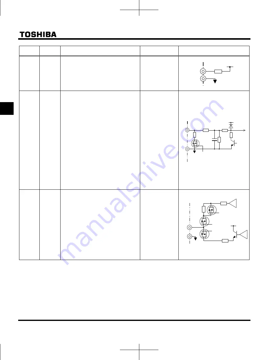
Inverter internal circuits
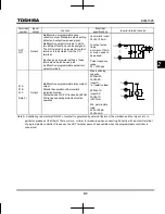
P5
Output
Analog power supply output
5Vdc
(permissible load
current: 10mA)
100
+5V
P5
CC
V I
Input
Multifunction programmable analog input.
Factory default setting: 0-10Vdc (1/1000
resolution) and 0-60Hz (0-50Hz)
frequency input.
The function can be changed to 0-20mAdc
(4-20mA) current input by parameter
=
1
setting.
0-5Vdc (1/1000 resolution) voltage input
by parameter
=
3
setting.
Switch to this setting when external
potentiometer is connected by using P5
terminal.
By changing parameter
f109
=
2
setting, this terminal can also be used as
a multifunction programmable logic input
terminal. When using the sink logic, be
sure to insert a resistor between P24-VI
(4.7 k
-1/2 W).
5V/10Vdc
(internal impedance:
40k
)
4-20mA
(internal
impedance: 250
)
Note 1)
1.6k
+5V
250
39.2k
47k
47k
ON:Current
OFF:Voltage
ON:10V
OFF:5V
VI
CC
FM Output
Multifunction programmable analog
output. Standard default setting: output
frequency.
The function can be changed to 0-10Vdc
voltage or 0-20mAdc (4-20mA) current
output by parameter
setting.
1mAdc full-scale
ammeter or
QS60T(option)
0-20mA (4-20mA)
DC ammeter
Permissible load
resistance:
750
Ω
or less
0-10V DC volt
meter
Permissible load
resistance:
1k
Ω
or more
2.7k
+24V
68
121
ON:Current
+
–
ON:Voltage
Meter
ON:Meter
+
–
FM
CC
Note 1) Be careful, if 4-20mA is selected, when the inverter's power is ON, the internal impedance is 250
Ω
, but when the power
is OFF, the internal impedance increases very much to approximately 40k
Ω
.

