E6582233
C-16
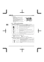
3
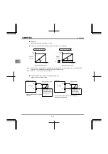
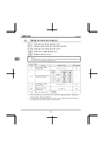
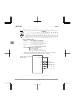
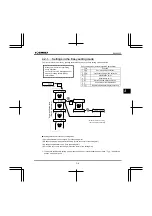
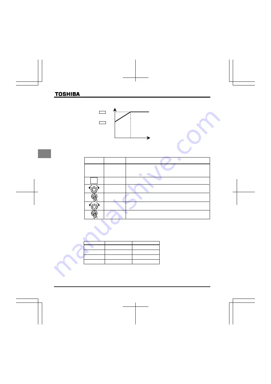
×0.6
×1.0
Output frequency (Hz)
Output current reduction factor
[%]/[A]
0
30Hz
Note: The motor overload protection start level is fixed at 30Hz.
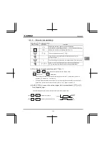
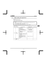
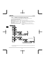
[Example of setting: When the VFNC3E-4007P is running with a 0.4kW motor having 1A rated current]
Operation
panel action
LED display
Operation
Displays the operation frequency. (Perform during operation
stopped.)
(When standard monitor display selection
is set to
0
[Operation frequency])
The first basic parameter “
” (history function) is displayed.
Turn the setting dial to change the parameter to
.
Parameter values can be read by pressing the center of the setting
dial (default setting is 100%).
Turn the setting dial to change the parameter to
% (= motor
rated current/inverter output rated current
×
100=1.0/2.3
×
100)
⇔
Press the center of the setting dial to save the changed parameter.
and the parameter are displayed alternately.
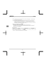
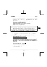
Note: The rated output current of the inverter should be calculated from the rated current for frequencies
below 4kHz, regardless of the setting of the PWM carrier frequency parameter (
).
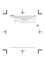
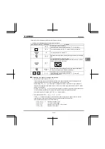
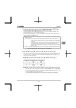
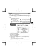
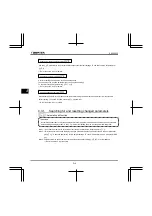
[Using a VF motor (motor for use with inverter)]
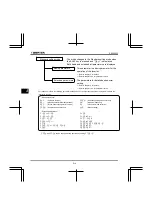
Setting of electronic thermal protection characteristics selection
Setting value
Overload protection
Overload stall
valid invalid
valid valid
invalid invalid
invalid valid
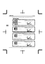
VF motors (motors designed for use with inverters) can be used in frequency ranges lower than those
for standard motors, but their cooling efficiency decreases at frequencies below 6Hz.
MODE


