E6582233
E-6
5
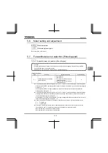
☆
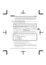
Setting acceleration/deceleration time (
,
) in conformance with mean load allows optimum
setting that conforms to further changes in load.
☆
Use this parameter after actually connecting the motor.
☆
When the inverter is used with a load that fluctuates considerably, it may fail to adjust the acceleration or
deceleration time in time, and therefore may be tripped.
☆
Do not use
=
when using a brake module (optional).
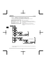
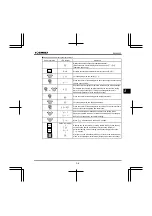
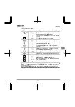
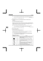
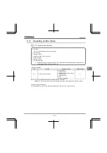
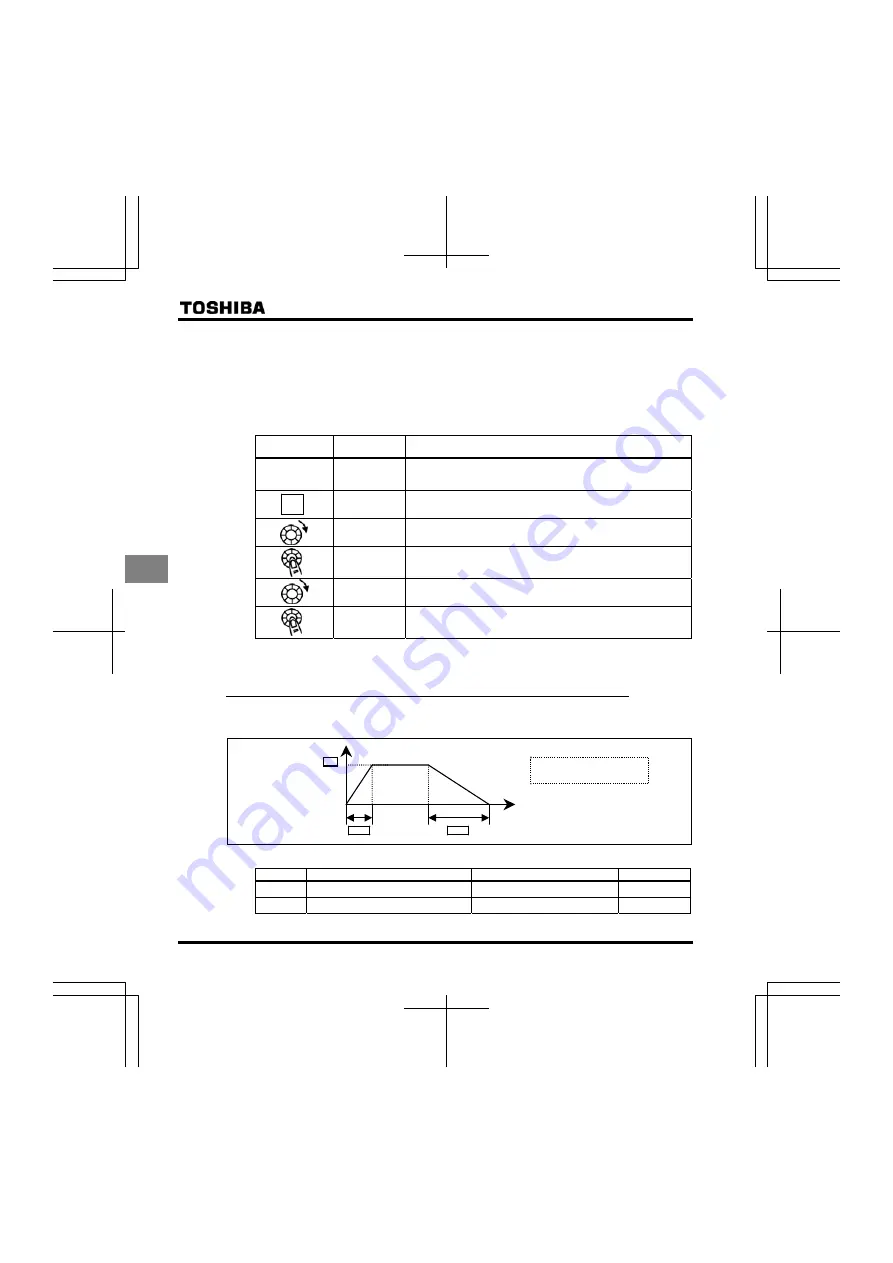
[Methods of setting automatic acceleration/deceleration]
Operation panel
action
LED display
Operation
Displays the operation frequency.
(When standard monitor display selection
is set to
[Operation frequency])
The first basic parameter “
” (history function) is displayed.
Turn the setting dial to the right to change the parameter to
.
Parameter values can be read by pressing the center of the setting
dial.
Turn the setting dial to the right to change the parameter to or
.
Press the center of the setting dial to save the changed parameter.
and the parameter are displayed alternately.
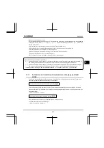
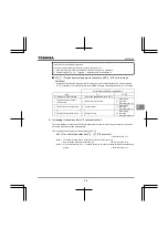
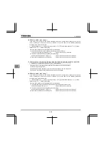
☆
Assigning the forced detection command (function number 122, 123) to any logic input terminal, it can be
changed automatic detection on a mandatory.
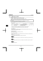
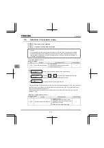
5.3.2
Manually setting acceleration/deceleration time
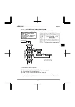
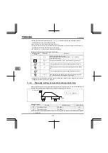
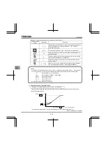
Set acceleration time from 0.0 (Hz) operation frequency to maximum frequency
and deceleration time as
the time when operation frequency goes from maximum frequency
to 0.0 (Hz).
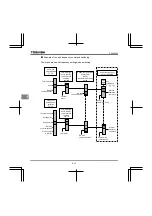
Output frequency (Hz)
Time [sec]
O
(Manual)
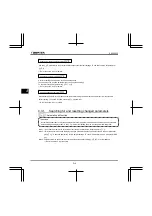
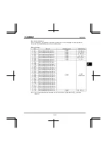
[Parameter setting]
Title Function
Adjustment range
Default setting
Acceleration time 1
0.0-3000 s
10.0
Deceleration time 1
0.0-3000 s
10.0
Note: When the acceleration/deceleration time is set to 0.0 seconds, the inverter accelerates and decelerates
0.05 seconds.
MODE

