E6582175
H-9
8
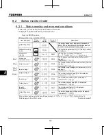
Note 6: Overload characteristic of inverter and region setting are displayed on the monitor as follows;
c
-xx :
aul
=
1
(Constant torque characteristic) is selected.
v
-xx :
aul
=
2
(Variable torque characteristic) is selected.
x-
eu
: Setup menu is selected to
eu
.
x-
as
: Setup menu is selected to
asia
.
x-
us
: Setup menu is selected to
usa
.
x-
jp
: Setup menu is selected to
jp
.
Note 7: Past trip records are displayed in the following sequence: 1 (latest trip record)
2
3
4
5
6
7
8
(oldest trip record). If no trip occurred in the past, the message “
” will be displayed. Details on
past trip record 1 to 8 can be displayed by pressing the center of the setting dial when past trip 1 to 8 is
displayed. Refer to section 8.2.2 for details.
Note 8: Parts replacement alarm is displayed based on the value calculated from the annual average ambient
temperature specified using
, the ON time of the inverter, the operating time of the motor and the
output current (load factor). Use this alarm as a guide only, since it is based on a rough estimation.
Note 9: The cumulative operation time increments only when the machine is in operation.
Note 10: If there is no trip record,
nerr
is displayed.
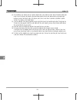
Note 11: Of the items displayed on the monitor, the reference values of items expressed in percent are listed below.
Output current: The current monitored is displayed in percentage. The value indicated on the
nameplate is 100%. The unit can be switched to A (amperes).
Input voltage:
The voltage displayed is the voltage determined by converting the voltage
measured in the DC section into an AC voltage. The reference value (100%
value) is 200V (240V class), 400V (500V class). The unit can be switched to V
(volts).
Output voltage:
The voltage displayed is the output command voltage. The reference value
(100% value) is 200V (240V class), 400V (500V class). This unit can be
switched to V (volts).
Load factor of inverter: Depending on the PWM carrier frequency (
f300
) setting and so on, the
actual rated current may become smaller than the rated output current
indicated on the nameplate. With the actual rated current at that time (after a
reduction) as 100%, the proportion of the load current to the rated current is
indicated in percent. The load factor is also used to calculate the conditions
for overload trip (
).
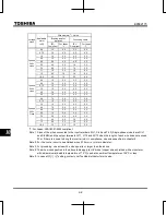
Note 12: Status monitor of * mark is displayed by
to
and
setting. The left side character
is as following table by each parameter setting number.
Summary of Contents for TOSVERT VF-S15 series
Page 394: ......


