


113
7
7
7
7.
.
.
.3
3
3
3
Usage of Digital I/O unit
Usage of Digital I/O unit
Usage of Digital I/O unit
Usage of Digital I/O unit
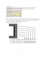
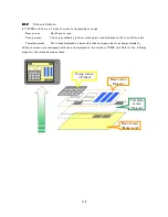
Digital I/O unit need not settings. Connect unit, Allocate Expansion I/O unit, and add I/O tags, then you can use
I/O of Expansion I/O unit as XW/YW tags (as register), or X/Y tags (as bit/coil).
One I/O register is composed 16 bit/coil. Each bit/coil corresponds to I/O contacts. If I/O of the unit is less
than 16 points (such as TR PDIO0808, etc), only lower 8bits of the I/O register is used.
Summary of Contents for TR PMIU
Page 11: ...1 Chapter Chapter Chapter Chapter 1 1 1 1 Introduction Introduction Introduction Introduction ...
Page 15: ...5 Chapter 2 Chapter 2 Chapter 2 Chapter 2 Hardware Hardware Hardware Hardware ...
Page 23: ...13 Input Wiring for TR PDIO0808 P Output ...
Page 24: ...14 Wiring for TR PDIO0808 N Input Output ...
Page 26: ...16 Input Input Wiring for TR PDIX1600 ...
Page 28: ...18 Output Wiring for TRSDOX0016N ...
Page 39: ...29 Chapter Chapter Chapter Chapter 3 3 3 3 TR PGMS TR PGMS TR PGMS TR PGMS ...
Page 83: ...73 Chapter 5 Chapter 5 Chapter 5 Chapter 5 Tag Tag Tag Tag ...
Page 98: ...88 Chapter Chapter Chapter Chapter 6 6 6 6 Task Task Task Task ...
Page 124: ...114 Chapter 8 Chapter 8 Chapter 8 Chapter 8 Screen Screen Screen Screen ...
Page 167: ...157 Note for the numbers of alarm message ...
Page 176: ...166 Appendix Appendix Appendix Appendix ...
Page 181: ...171 ...
Page 182: ...172 ...


