


24
2
2
2
2.
.
.
.5
5
5
5.
.
.
.2
2
2
2
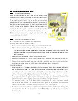
When any error is detected
PMIU unit has self diagnosis function and checking itself every scanning. If any error is detected and cannot
recover the error by retries, PMIU unit switches to HALT mode. You can refer history and detail of error by
Event history, and current status can referred by system tags.
There is a kind of error shown below.
Unit Error
Watchdog timer error of micro processor built in PMIU unit. System coil M0016 (CPU error) and M0027
(Watchdog timer error) changes to ON.
I/O mismatch
The allocation (installed slot number) or the type of Expansion I/O unit is different from project. System coil
M0017 (I/O error) and M0029 (I/O mismatch error) changes to ON.
When this error is detected in power ON, PMIU unit becomes HALT mode. To switch the unit to RUN mode
forcibly, press F1 key twice, or connect USB cable to unit, switch ONLINE mode and select “RUN” from
“PLC Control” from “Mode” menu of menu bar. Then the PMIU unit becomes to Forced RUN mode. In this
mode, ladder and application of project is executed even if I/O unit is different from project or not attached,
but I/O scan and refresh is not done. POWER LED is blinking.
I/O bcc error
Parity error is detected at Expansion I/O unit or data bus of Expansion port. System coil M0017 (I/O error)
and M0031 (I/O communication error) changes to ON.
Program Error
Scan time is exceeds 200mSec (in default. You can extend it to 350mSec by using WDT reset instruction in
ladder block). System coil M0018 (Program error) and M0031 (Ladder scan time over) changes to ON.
Clock calendar error
The data of built-in RTC is invalid. System coil M0021 (Clock/calendar illegal value warning) changes to ON.
Retentive data loss
The data of retentive memory area is invalid. If this error is detected, data validity of retentive area is not
guaranteed. System coil M0022 (Clock/calendar illegal value warning) changes to ON.
When the power of PMIU unit is ON, this item is checked at only once.
Summary of Contents for TR PMIU
Page 11: ...1 Chapter Chapter Chapter Chapter 1 1 1 1 Introduction Introduction Introduction Introduction ...
Page 15: ...5 Chapter 2 Chapter 2 Chapter 2 Chapter 2 Hardware Hardware Hardware Hardware ...
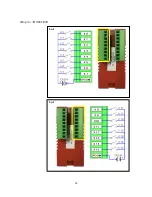
Page 23: ...13 Input Wiring for TR PDIO0808 P Output ...
Page 24: ...14 Wiring for TR PDIO0808 N Input Output ...
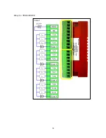
Page 26: ...16 Input Input Wiring for TR PDIX1600 ...
Page 28: ...18 Output Wiring for TRSDOX0016N ...
Page 39: ...29 Chapter Chapter Chapter Chapter 3 3 3 3 TR PGMS TR PGMS TR PGMS TR PGMS ...
Page 83: ...73 Chapter 5 Chapter 5 Chapter 5 Chapter 5 Tag Tag Tag Tag ...
Page 98: ...88 Chapter Chapter Chapter Chapter 6 6 6 6 Task Task Task Task ...
Page 124: ...114 Chapter 8 Chapter 8 Chapter 8 Chapter 8 Screen Screen Screen Screen ...
Page 167: ...157 Note for the numbers of alarm message ...
Page 176: ...166 Appendix Appendix Appendix Appendix ...
Page 181: ...171 ...
Page 182: ...172 ...


