


74
5
5
5
5.
.
.
.1
1
1
1
About T
About T
About T
About Tag
ag
ag
ag
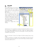
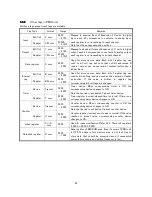
In TR series, all registers and bits/coils are defined and managed as "Tag", and registered “Tag Database”.
5
5
5
5.
.
.
.1
1
1
1.
.
.
.1
1
1
1
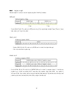
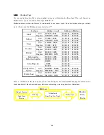
Relation between Coli/Bit and Register
In tag number, aWbbbb means register, abbbb means bit/coil (a is an alphabet corresponding to type of the tag,
b is tag number). Register tag is usually used to store data such as numerical value, ASCII code etc. Bit/coil tag
is usually used for store ON/OFF data such as the state of I/O, flag, etc.
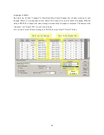
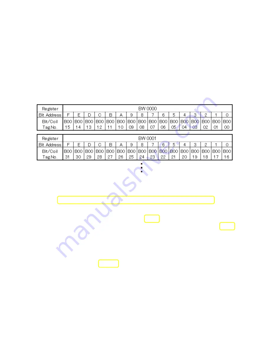
In single word (2byte) register, the image of the relation between the register and the bit is shown as an
example of the internal register below.
One word register can considered as one numerical value register tag or aggregate of 16bits bit/coil tags.
The relation between the tag number of the register and the tag number of the bit in the register is as follows.
(Register number) × 16 + (Bit order in decimal number) = (
Bit/Coil tag number
Bit/Coil tag number
Bit/Coil tag number
Bit/Coil tag number
)
For example,
BW 025 Bit 3
:
25×16 + 3 = 403, So device No. is B 0403
XW 001 Bit C
:
1×16 + 12 (hexadecimal “C” becomes decimal “12”) = 28, So device No. is X 0028
The first device address of the register (device of bit0) becomes the multiple of 16.
You can also define any bit of numerical value register tag such as D register. Tag number of these tags and bit
position have been delimited in under bar ( _ ).
For example,
D 0158 Bit F
:
device No. is D 0158
_
_
_
_
15
Note that this bit addressed register cannot use in ladder block.
Summary of Contents for TR PMIU
Page 11: ...1 Chapter Chapter Chapter Chapter 1 1 1 1 Introduction Introduction Introduction Introduction ...
Page 15: ...5 Chapter 2 Chapter 2 Chapter 2 Chapter 2 Hardware Hardware Hardware Hardware ...
Page 23: ...13 Input Wiring for TR PDIO0808 P Output ...
Page 24: ...14 Wiring for TR PDIO0808 N Input Output ...
Page 26: ...16 Input Input Wiring for TR PDIX1600 ...
Page 28: ...18 Output Wiring for TRSDOX0016N ...
Page 39: ...29 Chapter Chapter Chapter Chapter 3 3 3 3 TR PGMS TR PGMS TR PGMS TR PGMS ...
Page 83: ...73 Chapter 5 Chapter 5 Chapter 5 Chapter 5 Tag Tag Tag Tag ...
Page 98: ...88 Chapter Chapter Chapter Chapter 6 6 6 6 Task Task Task Task ...
Page 124: ...114 Chapter 8 Chapter 8 Chapter 8 Chapter 8 Screen Screen Screen Screen ...
Page 167: ...157 Note for the numbers of alarm message ...
Page 176: ...166 Appendix Appendix Appendix Appendix ...
Page 181: ...171 ...
Page 182: ...172 ...


