


MOBILE COMMUNICATIONS DIVISION
CUSTOMER SERVICES
Version 1.0 22/11/2006
Created by Konrad Szombara
Page 65 of 103
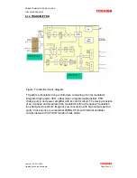
6.1.5 RECEIVER
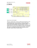
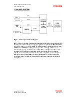
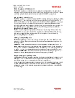
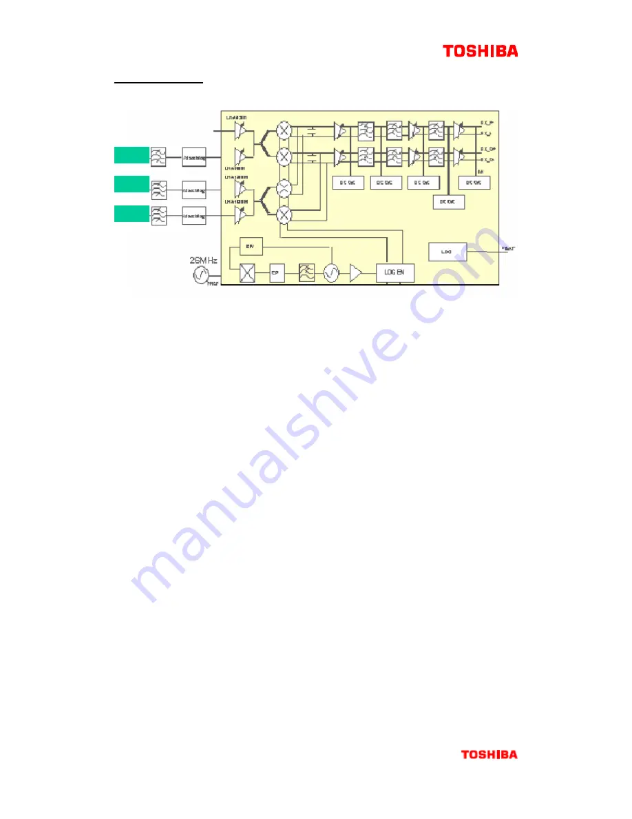
Figure Receiver block diagram
RX path is a direction down conversion architecture that eliminates the need
for Intermediate Frequency (IF) components. The device includes three
bands integrated LNAS, a quadrate demodulator, baseband amplifier circuit
with I/Q outputs and three stages of DC-offset correction. The DCOC
correction loop ensures DC-offsets, generated in SKY74117, do not overload
baseband chain. The receiver can be calibrated to optimize IP2 performance,
which ensures limited baseband interfering signal amplitude. The SKY74117
also features an integrated, fully programmable, sigma-delta fraction-N
synthesizer suitable for GPRS multi-slot operation.
GSM
DCS
PCS