Table of Contents
vi
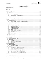
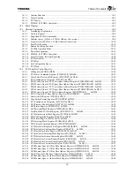
11.4.5
FIFO Control Register 0 (SIFCR0) 0xF310 (Ch. 0)
FIFO Control Register 1 (SIFCR1) 0xF410 (Ch. 1) .........................................................................11-20
11.4.6
Flow Control Register 0 (SIFLCR0) 0xF314 (Ch. 0)
Flow Control Register 1 (SIFLCR1) 0xF414 (Ch. 1) .......................................................................11-21
11.4.7
Baud Rate Control Register 0 (SIBGR0) 0xF318 (Ch. 0)
Baud Rate Control Register 1 (SIBGR1) 0xF418 (Ch. 1) ................................................................11-22
11.4.8
Transmit FIFO Register 0 (SITFIFO0) 0xF31C (Ch. 0)
Transmit FIFO Register 1 (SITFIFO1) 0xF41C (Ch. 1) ...................................................................11-23
11.4.9
Receive FIFO Register 0 (SIRFIFO0) 0xF320 (Ch. 0)
Receive FIFO Register 1 (SIRFIFO1) 0xF420 (Ch. 1).....................................................................11-24
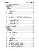
12.
Timer/Counter....................................................................................................................................................... 12-1
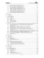
12.1
Features ........................................................................................................................................................ 12-1
12.2
Block Diagram ............................................................................................................................................. 12-2
12.3
Detailed Explanation.................................................................................................................................... 12-3
12.3.1
Overview ........................................................................................................................................... 12-3
12.3.2
Counter Clock.................................................................................................................................... 12-3
12.3.3
Counter .............................................................................................................................................. 12-4
12.3.4
Interval Timer Mode .......................................................................................................................... 12-4
12.3.5
Pulse Generator Mode ....................................................................................................................... 12-6
12.3.6
Watchdog Timer Mode ...................................................................................................................... 12-7
12.4
Registers....................................................................................................................................................... 12-9
12.4.1
Timer Control Register
n
(TMTCRn) TMTCR0 0xF000 TMTCR1 0xF100 TMTCR2 0xF200 ... 12-10
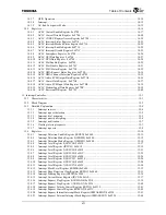
12.4.2
Timer Interrupt Status Register
n
(TMTISRn) TMTISR0 0xF004 TMTISR1 0xF104
TMTISR2 0xF204 ............................................................................................................................12-11
12.4.3
Compare Register An (TMCPRAn) TMCPRA0 0xF008 TMCPRA1 0xF108
TMCPRA2 0xF208.......................................................................................................................... 12-12
12.4.4
Compare Register Bn (TMCPRBn) TMCPRB0 0xF00C TMCPRB1 0xF10C .............................. 12-13
12.4.5
Interval Timer Mode Register
n
(TMITMRn) TMITMR0 0xF010 TMITMR1 0xF110
TMITMR2 0xF210 .......................................................................................................................... 12-14
12.4.6
Divide Register
n
(TMCCDRn) TMCCDR0 0xF020 TMCCDR1 0xF120 TMCCDR2 0xF220 .. 12-15
12.4.7
Pulse Generator Mode Register
n
(TMPGMRn) TMPGMR0 0xF000 TMPGMR1 0xF130 ........ 12-16
12.4.8
Watchdog Timer Mode Register
n
(TMWTMRn) TMWTMR2 0xF240 ....................................... 12-17
12.4.9
Timer Read Register
n
(TMTRRn) 0xF0F0 TMTRR0 0xF0F0 TMTRR1 0xF1F0
TMTRR2 0xF2F0 ............................................................................................................................ 12-18
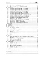
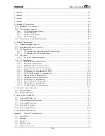
13.
Parallel I/O Port .................................................................................................................................................... 13-1
13.1
Characteristics.............................................................................................................................................. 13-1
13.2
Block Diagram ............................................................................................................................................. 13-1
13.3
Detailed Description .................................................................................................................................... 13-2
13.3.1
Selecting PIO Pins ............................................................................................................................. 13-2
13.3.2
General-purpose Parallel Port ............................................................................................................ 13-2
13.4
Registers....................................................................................................................................................... 13-2
13.4.1
PIO Output Data Register (PIODO) 0xF500 ..................................................................................... 13-3
13.4.2
PIO Input Data Register (PIODI) 0xF504 ......................................................................................... 13-3
13.4.3
PIO Direction Control Register (PIODIR) 0xF508 ........................................................................... 13-4
13.4.4
PIO Open Drain Control Register (XPIOOD) 0xF50C ..................................................................... 13-4
14.
AC-link Controller................................................................................................................................................ 14-1
14.1
Features ........................................................................................................................................................ 14-1
14.2
Configuration ............................................................................................................................................... 14-2
14.3
Functional Description................................................................................................................................. 14-3
14.3.1
CODEC Connection .......................................................................................................................... 14-3
14.3.2
Boot Configuration ............................................................................................................................ 14-4
14.3.3
Usage Flow ........................................................................................................................................ 14-5
14.3.4
AC-link Start Up................................................................................................................................ 14-7
14.3.5
CODEC Register Access ................................................................................................................... 14-8
14.3.6
Sample-data Transmission and Reception ......................................................................................... 14-9
Summary of Contents for TX49 TMPR4937
Page 1: ...64 Bit TX System RISC TX49 Family TMPR4937 Rev 2 0 ...
Page 4: ......
Page 13: ...Table of Contents ix TMPR4937 Revision History 1 ...
Page 14: ...Table of Contents x ...
Page 15: ...Handling Precautions ...
Page 16: ......
Page 18: ...1 Using Toshiba Semiconductors Safely 1 2 ...
Page 40: ...3 General Safety Precautions and Usage Considerations 3 18 ...
Page 42: ...4 Precautions and Usage Considerations 4 2 ...
Page 43: ...TMPR4937 2005 3 Rev 2 0 ...
Page 44: ......
Page 52: ...Chapter 1 Overview and Features 1 6 ...
Page 156: ...Chapter 7 External Bus Controller 7 56 ...
Page 491: ...Chapter 16 Removed 16 1 16 Removed ...
Page 492: ...Chapter 16 Removed 16 2 ...
Page 493: ...Chapter 17 Removed 17 1 17 Removed ...
Page 494: ...Chapter 17 Removed 17 2 ...
Page 495: ...Chapter 18 Removed 18 1 18 Removed ...
Page 496: ...Chapter 18 Removed 18 2 ...
Page 497: ...Chapter 19 Removed 19 1 19 Removed ...
Page 498: ...Chapter 19 Removed 19 2 ...
Page 506: ...Chapter 20 Extended EJTAG Interface 20 8 ...
Page 530: ...Chapter 22 Pinout and Package Information 22 10 ...
Page 542: ...Chapter 24 Parts Number when Ordering 24 2 ...


