Chapter 7 External Bus Controller
7-9
7.3.6 Access
Mode
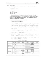
The following four modes are available as controller access modes. These modes can be set
separately for each channel.
•
Normal mode
•
Page mode
•
External ACK mode
•
Ready mode
Depending on the combination of modes in each channel, either of two modes in which the
ACK*/Ready signal operates differently (ACK*/Ready Dynamic mode, ACK*/Ready Static mode) is
selected by the ACK*/Ready Mode bit (CCFG.ARMODE) of the Chip Configuration Register. The
mode selected is applied globally to all channels.
(1) ACK*/READY Dynamic mode (CCFG.ARMODE = 0)
This mode is selected in the initial state.
The ACK*/Ready signal automatically switches to either input or output according to the setting of
each channel. When in the Normal mode or the Page mode, the ACK*/Ready signal is an output
signal, and the internally generated ACK* signal is output. When in the External ACK* or Ready
mode, the ACK*/Ready signal becomes an input signal. The ACK*/Ready signal outputs High if
there is no access to the External Bus Controller. However, this signal may output Low during
access to SDRAM.
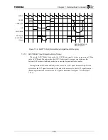
Please refer to the timing diagrams (Figure 7.5.23 and Figure 7.5.24) and be careful to avoid
conflicts when switching from output to input.
(2) ACK*/Ready Static mode (CCFG.ARMODE = 0)
The internally generated ACK* signal is not output when in either the Normal mode or Page mode.
Therefore, the ACK*/Ready signal will not become an output in any channel.
Access using Burst transfer by the internal bus (G-Bus) is supported when in a mode other than the
Ready mode. However, the Ready mode is not supported.
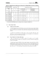
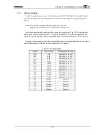
Table 7.3.7 Operation Mode
PM
RDY
PWT:WT
Mode
ACK
*
/READY
Pin State
Access End
Timing State
G-Bus Burst
Access
!3f Normal Output
Internally
Generated ACK
*
√
0
3f External
ACK
*
Input ACK
*
Input
√
0
1
⎯
READY Input Ready
Input
⎯
0
⎯
Page Output
Internally
Generated ACK
*
√
ACK
*
/Ready
Dynamic Mode
!0
1
⎯
Reserved
⎯
⎯
⎯
!3f Normal Hi-Z
Internally
Generated ACK
*
√
0
3f External
ACK
*
Input ACK
*
Input
√
0
1
⎯
READY Input Ready
Input
⎯
0
⎯
Page Hi-Z
Internally
Generated ACK
*
√
ACK
*
/Ready
Static Mode
!0
1
⎯
Reserved
⎯
⎯
⎯
Summary of Contents for TX49 TMPR4937
Page 1: ...64 Bit TX System RISC TX49 Family TMPR4937 Rev 2 0 ...
Page 4: ......
Page 13: ...Table of Contents ix TMPR4937 Revision History 1 ...
Page 14: ...Table of Contents x ...
Page 15: ...Handling Precautions ...
Page 16: ......
Page 18: ...1 Using Toshiba Semiconductors Safely 1 2 ...
Page 40: ...3 General Safety Precautions and Usage Considerations 3 18 ...
Page 42: ...4 Precautions and Usage Considerations 4 2 ...
Page 43: ...TMPR4937 2005 3 Rev 2 0 ...
Page 44: ......
Page 52: ...Chapter 1 Overview and Features 1 6 ...
Page 156: ...Chapter 7 External Bus Controller 7 56 ...
Page 491: ...Chapter 16 Removed 16 1 16 Removed ...
Page 492: ...Chapter 16 Removed 16 2 ...
Page 493: ...Chapter 17 Removed 17 1 17 Removed ...
Page 494: ...Chapter 17 Removed 17 2 ...
Page 495: ...Chapter 18 Removed 18 1 18 Removed ...
Page 496: ...Chapter 18 Removed 18 2 ...
Page 497: ...Chapter 19 Removed 19 1 19 Removed ...
Page 498: ...Chapter 19 Removed 19 2 ...
Page 506: ...Chapter 20 Extended EJTAG Interface 20 8 ...
Page 530: ...Chapter 22 Pinout and Package Information 22 10 ...
Page 542: ...Chapter 24 Parts Number when Ordering 24 2 ...

