Chapter 8 DMA Controller
8-7
8.3.3.2 Dual
Address
Transfer
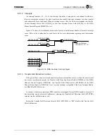
If the Single Address bit (DMCCRn.SNGAD) has been cleared, access to external I/O devices
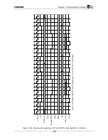
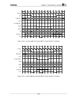
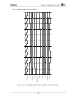
and to external memory is each performed continuously. Each access is the same as normal access
except when the DMAACK[n] signal is asserted.
Please refer to “8.3.8 Dual Address Transfer” for information regarding setting the register.
8.3.3.3 Single Address Transfer (Fly-by DMA)
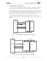
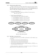
If the Single Address bit (DMCCRn.SNGAD) is set, either data reading from an external I/O
device and data writing to external memory or data reading from external memory and data
writing to an external I/O device is performed simultaneously. The following conditions must be
met in order to perform Single Address transfer.
•
The data bus widths of the external I/O device and external memory match
•
Data can be input/output to/from the external I/O device and external memory during the
same clock cycle
The Transfer Direction bit (MEMIO) of the DMA Channel Control Register (DMCCRn)
specifies the transfer direction.
•
From memory to an external I/O device (DMCCRn.MEMIO = “1”)
External memory Read operation to an address specified by the DMA Source Address
Register (DMSARn) is performed simultaneously to assertion of the DMAACK[n] signal.
•
Single Address transfer from memory to an external I/O device (DMCCRn.MEMIO = “0”)
External memory Write operation to an address specified by the DMA Source Address
Register (DMSARn) is performed simultaneously to assertion of the DMAACK[n] signal. At
this time, the external I/O device drives the DATA signal instead of the TX4937.
Special attention must be paid to the timing design when the bus clock frequency is high or
when performing Burst transfer. Single Address transfer using Burst transfer with SDRAM is not
recommended.
8.3.3.4 DMADONE
*
Signal
The DMADONE* signal operates as either the DMA stop request input signal or the DMA done
signalling output signal, or may operate as both of these signals depending on the setting of the
DONE Control Field (DNCTRL) of the DMA Channel Control Register (DMCCRn).
The DMADONE* signal is shared by four channels. The DMADONE* channel is valid for a
channel when the DMAACK[n] signal for that channel is asserted.
If the DMADONE* channel is set to be used as an output signal (DMCCRn.DNCTRL = 10/11),
it will operate as follows depending on the setting of the Chain End bit (CHDN) of the DMA
Channel Control Register (DMCCRn).
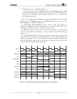
When the Chain End bit (CHDN) is set, the DMADONE* signal is only asserted when the
DMAACK[n] signal for the last DMA transfer in the Link List Command Chain is asserted.
Summary of Contents for TX49 TMPR4937
Page 1: ...64 Bit TX System RISC TX49 Family TMPR4937 Rev 2 0 ...
Page 4: ......
Page 13: ...Table of Contents ix TMPR4937 Revision History 1 ...
Page 14: ...Table of Contents x ...
Page 15: ...Handling Precautions ...
Page 16: ......
Page 18: ...1 Using Toshiba Semiconductors Safely 1 2 ...
Page 40: ...3 General Safety Precautions and Usage Considerations 3 18 ...
Page 42: ...4 Precautions and Usage Considerations 4 2 ...
Page 43: ...TMPR4937 2005 3 Rev 2 0 ...
Page 44: ......
Page 52: ...Chapter 1 Overview and Features 1 6 ...
Page 156: ...Chapter 7 External Bus Controller 7 56 ...
Page 491: ...Chapter 16 Removed 16 1 16 Removed ...
Page 492: ...Chapter 16 Removed 16 2 ...
Page 493: ...Chapter 17 Removed 17 1 17 Removed ...
Page 494: ...Chapter 17 Removed 17 2 ...
Page 495: ...Chapter 18 Removed 18 1 18 Removed ...
Page 496: ...Chapter 18 Removed 18 2 ...
Page 497: ...Chapter 19 Removed 19 1 19 Removed ...
Page 498: ...Chapter 19 Removed 19 2 ...
Page 506: ...Chapter 20 Extended EJTAG Interface 20 8 ...
Page 530: ...Chapter 22 Pinout and Package Information 22 10 ...
Page 542: ...Chapter 24 Parts Number when Ordering 24 2 ...


