Chapter 8 DMA Controller
8-27
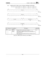
8.4.2
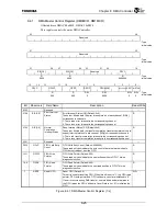
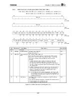
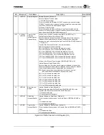
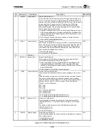
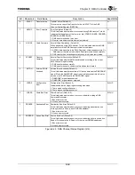
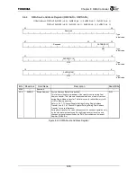
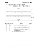
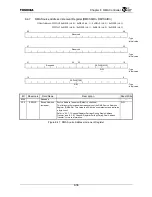
DMA Channel Control Register (DM0CCRn, DM1CCRn)
Offset address: DMAC0 0xB030 (ch. 0) / 0xB070 (ch. 1) / 0xB0B0 (ch. 2) / 0xB0F0 (ch. 3)
DMAC1 0xB830 (ch. 0) / 0xB870 (ch.1 ) / 0xB8B0 (ch. 2) / 0xB8F0 (ch. 3)
63
48
Reserved
: Type
: Initial value
47
32
Reserved
: Type
: Initial value
31 30 29 28 27 26 25 24 23 22 21 20 19 18 17 16
Reserved
IMMCHN
USEXFSZ
LE
DBINH SBINH CHRST
RVBYTE ACKPOL
REQPL EGREQ CHDN
DNCTL
EXTRQ
R/W R/W R/W R/W R/W R/W R/W R/W R/W R/W R/W
R/W
R/W : Type
0
0
⎯
0 0 1 0 0 0 0 0
00
0
: Initial value
15
13 12 11 10 9 8 7 6 5 4
2 1 0
STLTIME/INTRQD
INTENE INTENC
INTENT
CHNEN XFACT
Reserved
SMPCHN
XFSZ
MEMIO
SNGAD
R/W R/W
R/W
R/W R R/W R/W R/W R/W
R/W
: Type
000
0 0 0 0 0 0
000 0 0
: Initial value
Bit Mnemonic Field
Name
Description Read/Write
63:32 Reserved
⎯
29
IMMCHN
Immediate Chain Immediate Chain (Default: 0)
Always set this bit to “1”.
R/W
28 USEXFSZ
Transfer Set Size
Mode
Use Transfer Set Size (Default: 0)
Selects the DMA channel operation mode during Burst DMA transfer.
Refer to “8.3.7.2 Burst Transfer During Single Address Transfer” and
“8.3.8.2 Burst Transfer During Dual Address Transfer” for more
information.
1: The DMA Controller always transfers the amount of data set in
DMCCRn.XFSZ for each bus operation. Since alignment to the
boundary of the DMCCRn.XFSZ in the address is not forced when in
this mode, transfers that exceed 32-double-word boundaries are divided
into two operations.
0: The DMA Controller calculates the transfer size so the address set in
DMSARn and DMDARn (only during Dual Address transfer) can be
aligned to the boundary of the size set in DMCCRn.XFSZ, then
transfers data according to that size.
Note: In Dual Address Transfer mode, programming this bit to 1 is valid
only when both the contents of the DMSARn and the DMDARn are
on doubleword boundaries
and
the contents of the DMCNTRn is a
multiple of eight bytes.
R/W
27 LE
Little
Endian
Little Endian (Default: value that is the opposite of the G-Bus Endian
(CCFG.ENDIAN)
This bit sets the Endian of the channel. Please use the default value as is.
1: Channel operates in the Little Endian mode
0: Channel operates in the Big Endian mode
R/W
Figure 8.4.2 DMA Channel Control Register (1/4)
Summary of Contents for TX49 TMPR4937
Page 1: ...64 Bit TX System RISC TX49 Family TMPR4937 Rev 2 0 ...
Page 4: ......
Page 13: ...Table of Contents ix TMPR4937 Revision History 1 ...
Page 14: ...Table of Contents x ...
Page 15: ...Handling Precautions ...
Page 16: ......
Page 18: ...1 Using Toshiba Semiconductors Safely 1 2 ...
Page 40: ...3 General Safety Precautions and Usage Considerations 3 18 ...
Page 42: ...4 Precautions and Usage Considerations 4 2 ...
Page 43: ...TMPR4937 2005 3 Rev 2 0 ...
Page 44: ......
Page 52: ...Chapter 1 Overview and Features 1 6 ...
Page 156: ...Chapter 7 External Bus Controller 7 56 ...
Page 491: ...Chapter 16 Removed 16 1 16 Removed ...
Page 492: ...Chapter 16 Removed 16 2 ...
Page 493: ...Chapter 17 Removed 17 1 17 Removed ...
Page 494: ...Chapter 17 Removed 17 2 ...
Page 495: ...Chapter 18 Removed 18 1 18 Removed ...
Page 496: ...Chapter 18 Removed 18 2 ...
Page 497: ...Chapter 19 Removed 19 1 19 Removed ...
Page 498: ...Chapter 19 Removed 19 2 ...
Page 506: ...Chapter 20 Extended EJTAG Interface 20 8 ...
Page 530: ...Chapter 22 Pinout and Package Information 22 10 ...
Page 542: ...Chapter 24 Parts Number when Ordering 24 2 ...

