Chapter 10 PCI Controller
10-9
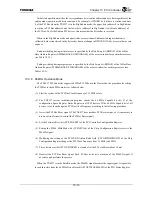
When expressed as a formula, conversion of a G-Bus address (GBusAddr[35:0]) into a PCI Bus
Address (PCIAddr[39:0]) is as follows below. GBASE[35:8], PBASE[39:8], and AM[35:8] each
represent the setting register of the corresponding access window indicated below in Table 10.3.2. The
“&” symbol indicates a logical AND for each bit, “||” indicates a logical OR for each bit, “!” indicates
logical NOT, and “|” indicates bit linking.
If (GBusAddr[35:8] & ! AM[35:8] == GBASE[35:8] & ! AM[35:8]) then
PCIAddr[39:0] = PBASE[39:36]
| ((PBASE[35:8] & ! AM[35:8]) || (GBusAddr[35:8] & AM[35:8]))
| GBusAddr[7:0];
Table 10.3.2 Initiator Access Space Address Mapping Register
G-Bus
Base
Address
GBASE[35:8]
PCI Bus Base Address
PBASE[39:8]
Address Mask
AM[35:8]
Memory Space 0
G2PM0GBASE.BA[35:8]
G2PM0PBASE.BA[39:8]
G2PM0MASK.AM[35:8]
Memory Space 1
G2PM1GBASE.BA[35:8]
G2PM1PBASE.BA[39:8]
G2PM1MASK.AM[35:8]
Memory Space 2
G2PM2GBASE.BA[35:8]
G2PM2PBASE.BA[39:8]
G2PM2MASK.AM[35:8]
I/O Space
G2PIOGBASE.BA[35:8]
G2PIOPBASE.BA[39:8]
G2PIOMASK.AM[35:8]
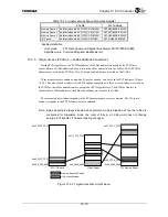
Figure 10.3.4 illustrates this address conversion.
Figure 10.3.4 Address Conversion For Initiator (G-Bus
→
PCI Bus Address Conversion)
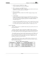
It is possible to set each space to valid/invalid or to perform Word Swap (see “10.3.7 Endian
Switching Function). Table 10.3.3 shows the settings registers for these properties.
When 64-bit access is made to the initiator memory space, two 32-bit Burst accesses are issued on the
PCI Bus. 64-bit access to the I/O space is not supported.
Also, operation is not guaranteed if resources in the PCI space were made cacheable and were then
accessed when the Critical Word First function of the TX49/H3 core was enabled.
GBusAddr
0
35
0x00
0
35 7
8
Compare
GBASE
0x00
0
35 7
8
AM
0 0 0 - - - - - - - - - - - 0 0 1 1 1 - - - - - - - - - - - - - - - - - - - -
0x00
0
39 7
8
PBASE
0
39
PCIAddr
Summary of Contents for TX49 TMPR4937
Page 1: ...64 Bit TX System RISC TX49 Family TMPR4937 Rev 2 0 ...
Page 4: ......
Page 13: ...Table of Contents ix TMPR4937 Revision History 1 ...
Page 14: ...Table of Contents x ...
Page 15: ...Handling Precautions ...
Page 16: ......
Page 18: ...1 Using Toshiba Semiconductors Safely 1 2 ...
Page 40: ...3 General Safety Precautions and Usage Considerations 3 18 ...
Page 42: ...4 Precautions and Usage Considerations 4 2 ...
Page 43: ...TMPR4937 2005 3 Rev 2 0 ...
Page 44: ......
Page 52: ...Chapter 1 Overview and Features 1 6 ...
Page 156: ...Chapter 7 External Bus Controller 7 56 ...
Page 491: ...Chapter 16 Removed 16 1 16 Removed ...
Page 492: ...Chapter 16 Removed 16 2 ...
Page 493: ...Chapter 17 Removed 17 1 17 Removed ...
Page 494: ...Chapter 17 Removed 17 2 ...
Page 495: ...Chapter 18 Removed 18 1 18 Removed ...
Page 496: ...Chapter 18 Removed 18 2 ...
Page 497: ...Chapter 19 Removed 19 1 19 Removed ...
Page 498: ...Chapter 19 Removed 19 2 ...
Page 506: ...Chapter 20 Extended EJTAG Interface 20 8 ...
Page 530: ...Chapter 22 Pinout and Package Information 22 10 ...
Page 542: ...Chapter 24 Parts Number when Ordering 24 2 ...


