3 General Safety Precautions and Usage Considerations
3-6
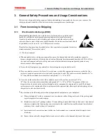
3.3 Design
Care must be exercised in the design of electronic equipment to achieve the desired reliability. It is important not
only to adhere to specifications concerning absolute maximum ratings and recommended operating conditions, it
is also important to consider the overall environment in which equipment will be used, including factors such as
the ambient temperature, transient noise and voltage and current surges, as well as mounting conditions which
affect device reliability. This section describes some general precautions which you should observe when
designing circuits and when mounting devices on printed circuit boards.
For more detailed information about each product family, refer to the relevant individual technical datasheets
available from Toshiba.
3.3.1 Absolute
maximum
ratings
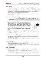
Do not use devices under conditions in which their absolute maximum ratings (e.g.
current, voltage, power dissipation or temperature) will be exceeded. A device may break
down or its performance may be degraded, causing it to catch fire or explode resulting in
injury to the user.
The absolute maximum ratings are rated values which must not be exceeded
during operation, even for an instant. Although absolute maximum ratings differ
from product to product, they essentially concern the voltage and current at each
pin, the allowable power dissipation, and the junction and storage temperatures.
If the voltage or current on any pin exceeds the absolute maximum rating, the
device’s internal circuitry can become degraded. In the worst case, heat generated
in internal circuitry can fuse wiring or cause the semiconductor chip to break
down.
If storage or operating temperatures exceed rated values, the package seal can deteriorate or the wires can
become disconnected due to the differences between the thermal expansion coefficients of the materials from
which the device is constructed.
3.3.2
Recommended operating conditions
The recommended operating conditions for each device are those necessary to guarantee that the device will
operate as specified in the datasheet.
If greater reliability is required, derate the device’s absolute maximum ratings for voltage, current, power and
temperature before using it.
3.3.3 Derating
When incorporating a device into your design, reduce its rated absolute maximum voltage, current, power
dissipation and operating temperature in order to ensure high reliability.
Since derating differs from application to application, refer to the technical datasheets available for the various
devices used in your design.
3.3.4 Unused
pins
If unused pins are left open, some devices can exhibit input instability problems, resulting in malfunctions such
as abrupt increase in current flow. Similarly, if the unused output pins on a device are connected to the power
supply pin, the ground pin or to other output pins, the IC may malfunction or break down.
Since the details regarding the handling of unused pins differ from device to device and from pin to pin, please
follow the instructions given in the relevant individual datasheets or databook.
Summary of Contents for TX49 TMPR4937
Page 1: ...64 Bit TX System RISC TX49 Family TMPR4937 Rev 2 0 ...
Page 4: ......
Page 13: ...Table of Contents ix TMPR4937 Revision History 1 ...
Page 14: ...Table of Contents x ...
Page 15: ...Handling Precautions ...
Page 16: ......
Page 18: ...1 Using Toshiba Semiconductors Safely 1 2 ...
Page 40: ...3 General Safety Precautions and Usage Considerations 3 18 ...
Page 42: ...4 Precautions and Usage Considerations 4 2 ...
Page 43: ...TMPR4937 2005 3 Rev 2 0 ...
Page 44: ......
Page 52: ...Chapter 1 Overview and Features 1 6 ...
Page 156: ...Chapter 7 External Bus Controller 7 56 ...
Page 491: ...Chapter 16 Removed 16 1 16 Removed ...
Page 492: ...Chapter 16 Removed 16 2 ...
Page 493: ...Chapter 17 Removed 17 1 17 Removed ...
Page 494: ...Chapter 17 Removed 17 2 ...
Page 495: ...Chapter 18 Removed 18 1 18 Removed ...
Page 496: ...Chapter 18 Removed 18 2 ...
Page 497: ...Chapter 19 Removed 19 1 19 Removed ...
Page 498: ...Chapter 19 Removed 19 2 ...
Page 506: ...Chapter 20 Extended EJTAG Interface 20 8 ...
Page 530: ...Chapter 22 Pinout and Package Information 22 10 ...
Page 542: ...Chapter 24 Parts Number when Ordering 24 2 ...

